Started 05/29/2005 finished 01/19/2006 Finished.
Hours worked this chapter :139.5 Holding off on running the brake
lines until the nose is complete where the lines connect to the brakes
master cylinders.
Start this chapter by adding Landing Gear reinforcement lay
up.
 In
this picture you can see I have already drilled the torque tube holes in the
landing gear bulk head. After this lay up I knife trimmed the holes open.
In
this picture you can see I have already drilled the torque tube holes in the
landing gear bulk head. After this lay up I knife trimmed the holes open.
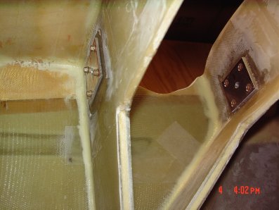
 Inside
the Landing Gear bay.
Inside
the Landing Gear bay.
 Firewall
and bulkhead lay up.
Firewall
and bulkhead lay up.
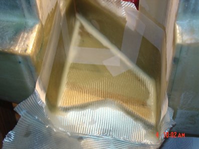
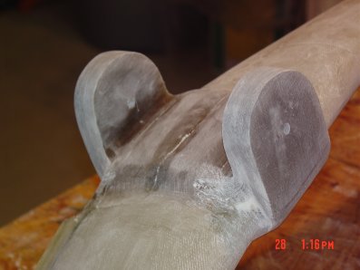
 The
strut is glassed with the peel ply
The
strut is glassed with the peel ply
 The
mess after the first lay up.
The
mess after the first lay up.
 A
little 5 minutes epoxy and some Mc D straws taped in place.
A
little 5 minutes epoxy and some Mc D straws taped in place.
 This
step was made easer by reading
Rick Maddy's builder
web site, he said lightly sanding the straws before hand which helps the
epoxy hold better. Thanks!
This
step was made easer by reading
Rick Maddy's builder
web site, he said lightly sanding the straws before hand which helps the
epoxy hold better. Thanks!
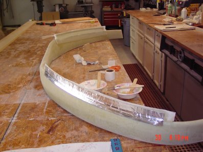 I
used the book method, which calls for aluminum foil taps the kind used on
air conditioning duck work. I had 6 layer of tap enough to make it good and
stiff.
I
used the book method, which calls for aluminum foil taps the kind used on
air conditioning duck work. I had 6 layer of tap enough to make it good and
stiff.
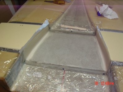
 Ready
for the second lay up, you can see the Mc Donald's straws I used for the
brake line conduit.
Ready
for the second lay up, you can see the Mc Donald's straws I used for the
brake line conduit.
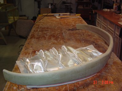
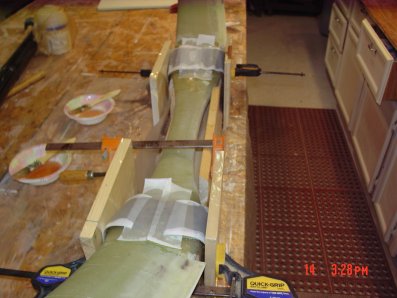
 You
can just see the nails I used to hold the strut in place. As I have read in
other builders web sites they added a block of wood in increase the height
off the workbench. This was a great plus that I recommend. The strut is
covered with the second lay up and peel & ply.
You
can just see the nails I used to hold the strut in place. As I have read in
other builders web sites they added a block of wood in increase the height
off the workbench. This was a great plus that I recommend. The strut is
covered with the second lay up and peel & ply.
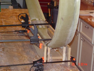
 Strut
is set up in the jig box, glass cut ready to do the tabs.
Strut
is set up in the jig box, glass cut ready to do the tabs.
 Marked
out the locations of the tabs on the jig box.
Marked
out the locations of the tabs on the jig box.
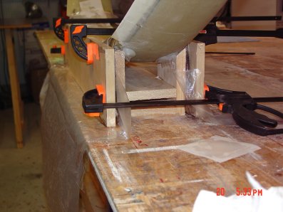
 After
all this work the clamping was to aggressive and the layers slid during
cure. One thing about glass is that you can cut it off before it's
fully cured and do it again. Next time I will use one long board on each
side with less clamping pressure.
After
all this work the clamping was to aggressive and the layers slid during
cure. One thing about glass is that you can cut it off before it's
fully cured and do it again. Next time I will use one long board on each
side with less clamping pressure.
 Second
time around was the charm.
Second
time around was the charm.
 True
and parallel next I drilled the pilot holes and removed the jig box and cut
the tabs to proper size.
True
and parallel next I drilled the pilot holes and removed the jig box and cut
the tabs to proper size.
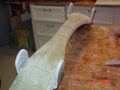 The
tabs are drilled and cut to proper size
The
tabs are drilled and cut to proper size
 You
can see the 1/4 pilot hole, inside is sanded ready for the inside lay
up.
You
can see the 1/4 pilot hole, inside is sanded ready for the inside lay
up.
 The
size of the glass was larger than needed as called for in the book, even
after I reduced the size by several inches it's still was a bit to much.
The
size of the glass was larger than needed as called for in the book, even
after I reduced the size by several inches it's still was a bit to much.
 Inside
tab before trimming.
Inside
tab before trimming.
 Here
is the inside tabs after trimming and sanding off any rough spots.
Here
is the inside tabs after trimming and sanding off any rough spots.
 One
thing I learned was to make sure that each layer was dry, because as you add
layers the epoxy builds up and can make the lay up to epoxy rich. I used the
5 layer on wax paper process and made sure that there where dry spots which
would pull in any extra epoxy. Squeegee between each layer helps remove and
distribute the epoxy.
One
thing I learned was to make sure that each layer was dry, because as you add
layers the epoxy builds up and can make the lay up to epoxy rich. I used the
5 layer on wax paper process and made sure that there where dry spots which
would pull in any extra epoxy. Squeegee between each layer helps remove and
distribute the epoxy.
 Here
are some shots of the plats with the 1/4 pilot hole. Floxed in place waiting
for cure.
Here
are some shots of the plats with the 1/4 pilot hole. Floxed in place waiting
for cure.
 Once
the strut tabs where finished I bored out the plats as called out in the
book and mounted the bushings. Everything lined up, what a bit of luck, I
was kind of worried I had missed something. It would of bend very difficult
to fix.
Once
the strut tabs where finished I bored out the plats as called out in the
book and mounted the bushings. Everything lined up, what a bit of luck, I
was kind of worried I had missed something. It would of bend very difficult
to fix.
 Final
tab lay up with bushings in place.
Final
tab lay up with bushings in place.
 Fit
foam to fill the gap, macro in place, also you can see the dimpling on the MKMGA under the bid glass. Finished the tabs by trimming the excess glass now ready
test fit.
Fit
foam to fill the gap, macro in place, also you can see the dimpling on the MKMGA under the bid glass. Finished the tabs by trimming the excess glass now ready
test fit.
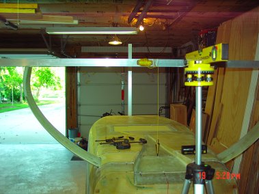 Here
you can see the laser level I used to make sure that the strut and axle
mounting hard point are level and true with the proper amount of toe in. The
toe in is very important this keeps the strut from splaying during landing
and normal operation. If you have to much toe in the wear on the wheels will
be excessive.
Here
you can see the laser level I used to make sure that the strut and axle
mounting hard point are level and true with the proper amount of toe in. The
toe in is very important this keeps the strut from splaying during landing
and normal operation. If you have to much toe in the wear on the wheels will
be excessive.
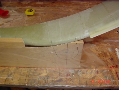
 These
two picture show the wood used to make the flat area on the strut where the
axle will be located. In this step you make sure that the toe in is set.
After cure you can sand it during the fine tuning process.
These
two picture show the wood used to make the flat area on the strut where the
axle will be located. In this step you make sure that the toe in is set.
After cure you can sand it during the fine tuning process.
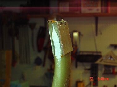
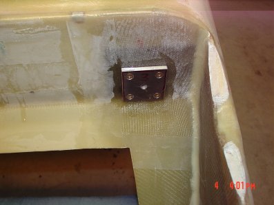
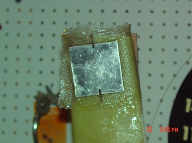 This
is the hard point on the inside of the strut.
This
is the hard point on the inside of the strut.
 These
next two picture you can see the strut has been cut to accommodate the axle
and brake. You can also see the surface has been sanded to set the toe in
alignment.
These
next two picture you can see the strut has been cut to accommodate the axle
and brake. You can also see the surface has been sanded to set the toe in
alignment.
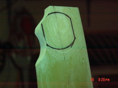 The
black outline is the axle base, I used it to make sure I removed just enough
of the strut for the brake.
The
black outline is the axle base, I used it to make sure I removed just enough
of the strut for the brake.
 In
this picture show the axle is mounted and the toe in is checked again. At
this point you also fit and mount the brake system.
In
this picture show the axle is mounted and the toe in is checked again. At
this point you also fit and mount the brake system.
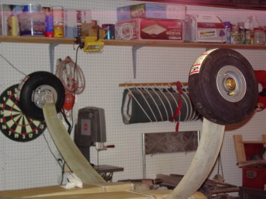
 Wheel
and brakes mounted, I will finish the brake line and add the heat protection
later, most likely during assembly in the fuselage.
Wheel
and brakes mounted, I will finish the brake line and add the heat protection
later, most likely during assembly in the fuselage.
 Test
fit and check of toe in using the laser and the tick marks on the door you
saw earlier.
Test
fit and check of toe in using the laser and the tick marks on the door you
saw earlier.
 Strut
finished waiting to be mounted in fuselage. This will happen once the nose
gear is finished.
Strut
finished waiting to be mounted in fuselage. This will happen once the nose
gear is finished.
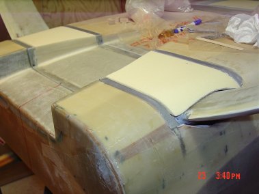
 After
shaping the foam the NASA scoop area is glassed.
After
shaping the foam the NASA scoop area is glassed.
 The
NASA scoop near the landing gear not yet shaped to the fuselage. (Camera
failure cause blur)
The
NASA scoop near the landing gear not yet shaped to the fuselage. (Camera
failure cause blur)
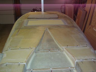
 Cover
shaped and test landing gear fit.
Cover
shaped and test landing gear fit.
 Cover
glassed with flox edges.
Cover
glassed with flox edges.
 Screw
holes with counter sink finished.
Screw
holes with counter sink finished.
 Starting
the speed brake removed from fuselage. Here I made it easer on myself by
take the suggestion from other builders web site and cute the glass while it
was still green, leaving some points to hold it in place.
Starting
the speed brake removed from fuselage. Here I made it easer on myself by
take the suggestion from other builders web site and cute the glass while it
was still green, leaving some points to hold it in place.
 Here
I am testing the linear motor, I need to find the full cycle limits to
determine the location of the hard point. The hard point is made from 1/4
aluminum with a plywood face plate just like the hinge hard point called out
in the book for the hinge.
Here
I am testing the linear motor, I need to find the full cycle limits to
determine the location of the hard point. The hard point is made from 1/4
aluminum with a plywood face plate just like the hinge hard point called out
in the book for the hinge.
 I
floxed in the hard point you can see the white dots are silicon plugs that
will prevent epoxy from entering the bolt holes. Once the 4 layer
reinforcement is cured I just drilled out the glass and then pick out the
plugs, it worked nice.
I
floxed in the hard point you can see the white dots are silicon plugs that
will prevent epoxy from entering the bolt holes. Once the 4 layer
reinforcement is cured I just drilled out the glass and then pick out the
plugs, it worked nice.
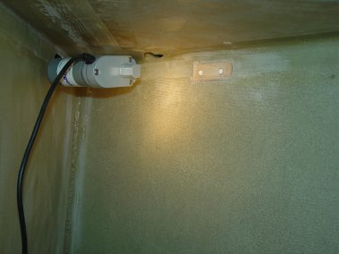
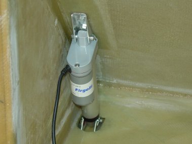 Here
is the finished inside. I got the Linear Actuator from
Firgelli-Automations.
Here
is the finished inside. I got the Linear Actuator from
Firgelli-Automations.
 Here
are some picture of the finished outside, I made the wood insert 1/2 inch
wider than called for, glad I did.
Here
are some picture of the finished outside, I made the wood insert 1/2 inch
wider than called for, glad I did.
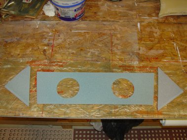 Here
are the parts for the landing bulk head cover. I used a paint can to
determine the size of the two holes. Not much detail in the book.
Here
are the parts for the landing bulk head cover. I used a paint can to
determine the size of the two holes. Not much detail in the book.
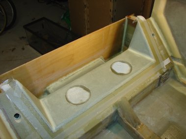 Installed
landing gear bulkhead, after cure I cut out the holes and remove some foam
from the edges of the hole to make room for some flox.
Installed
landing gear bulkhead, after cure I cut out the holes and remove some foam
from the edges of the hole to make room for some flox.
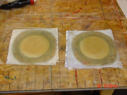 Landing
gear bulkhead covers.
Landing
gear bulkhead covers.
 Landing
gear covers installed.
Landing
gear covers installed.
On to Chapter 10
