Matco master brake cylinders.
 Here
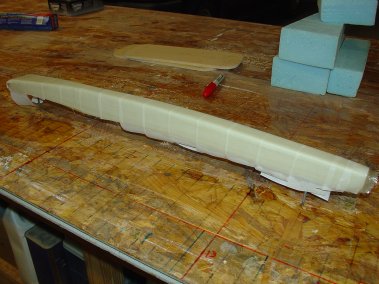
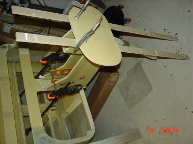
you can see the strut temporally mounted on two screws on my work table top,
I used 5 min. epoxy. After the glass is cured a sharp rap on each screw
breaks the strut loose, worked out nicely.
Here
you can see the strut temporally mounted on two screws on my work table top,
I used 5 min. epoxy. After the glass is cured a sharp rap on each screw
breaks the strut loose, worked out nicely.
 There
has been some issues with NG30 so I am following the design change
recommendations.
There
has been some issues with NG30 so I am following the design change
recommendations.
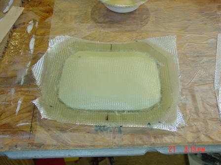
 Cut
foam to new dimensions and started glassing pivot point for landing gear.
Cut
foam to new dimensions and started glassing pivot point for landing gear.
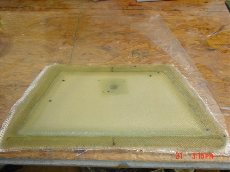
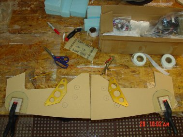 Marking
location for
EZ-Noselift hard points and the hard points for landing gear pivot floxed.
Marking
location for
EZ-Noselift hard points and the hard points for landing gear pivot floxed.
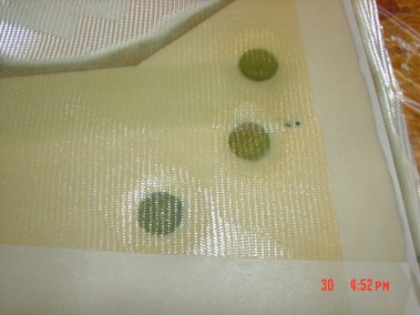
 Glassing
inside with the additional bid strips.
Glassing
inside with the additional bid strips.
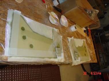
 Glassing
out side with bid strips and hard points for power retraction system.
Glassing
out side with bid strips and hard points for power retraction system.
 Hard
points used to mount the
EZ-Noselift hardware.
Hard
points used to mount the
EZ-Noselift hardware.
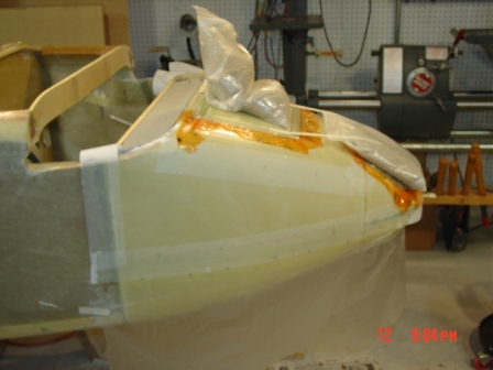
 NG30
outside finished glass.
NG30
outside finished glass.
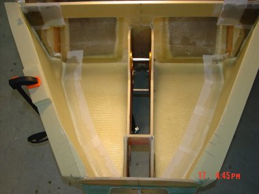
 Removed
foam and glass inside of landing gear pivot location on NG30.
Removed
foam and glass inside of landing gear pivot location on NG30.
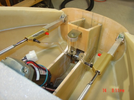
 Flox
the strut to the pivot bearing making sure it is centered in between NG30s.
Flox
the strut to the pivot bearing making sure it is centered in between NG30s.
 Clamp
until flox is cured.
Clamp
until flox is cured.
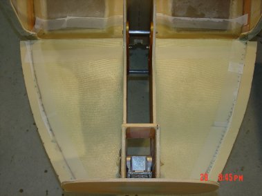
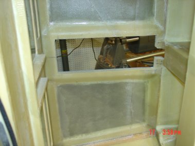
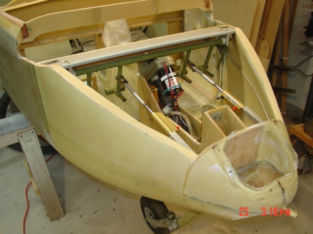
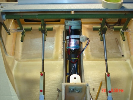
 In
this picture you can see the 1/4" plate in front of the bearing and the
attachment point of the landing gear actuator.
In
this picture you can see the 1/4" plate in front of the bearing and the
attachment point of the landing gear actuator.
 Test
fit of F0 with NG30, you can see the foam part f6 I am using the cut out
from the main spar access openings.
Test
fit of F0 with NG30, you can see the foam part f6 I am using the cut out
from the main spar access openings.
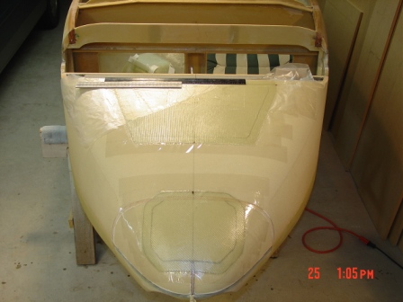
 Glassed
F0 with NG30 assembly.
Glassed
F0 with NG30 assembly.
 Mounting
NG30 to fuselage
Mounting
NG30 to fuselage
 Carved
and added nose bottoms using thick macro.
Carved
and added nose bottoms using thick macro.
 Glassed
bottom inside up to where the sides will attach, so you do not hit the glass
when carving the sides.
Glassed
bottom inside up to where the sides will attach, so you do not hit the glass
when carving the sides.
 You
can see the glass runs on to the floor back past f22.
You
can see the glass runs on to the floor back past f22.
 Nose
bulkhead glassed and peel ply.
Nose
bulkhead glassed and peel ply.
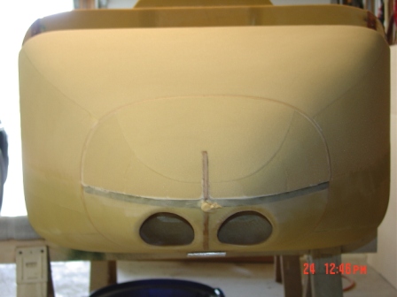
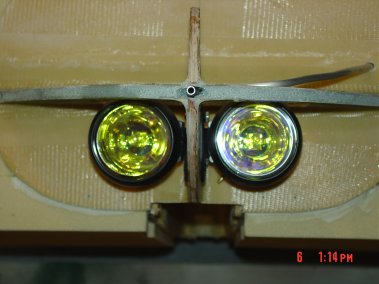 I
am using the ballast box location for my landing lights.
I
am using the ballast box location for my landing lights.
 These
lights are 55w halogen each, focused beam. I used a tube bender to get the
pitot tube just right so it fits without being in the way of the lights and
is sloping up.
These
lights are 55w halogen each, focused beam. I used a tube bender to get the
pitot tube just right so it fits without being in the way of the lights and
is sloping up.
 Sides
macro in place and inside glassed.
Sides
macro in place and inside glassed.
 One
side required a little clamping pressure to hold in place for cure.
One
side required a little clamping pressure to hold in place for cure.
 As
you can see I am going to have landing gear doors for the front wheel well.
As
you can see I am going to have landing gear doors for the front wheel well.
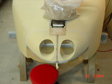
 In
this picture you can see how the lights fit in the ballast box and the
bracket that will hold the brake fluid reservoir. I am using Matco master
cylinders.
In
this picture you can see how the lights fit in the ballast box and the
bracket that will hold the brake fluid reservoir. I am using Matco master
cylinders.
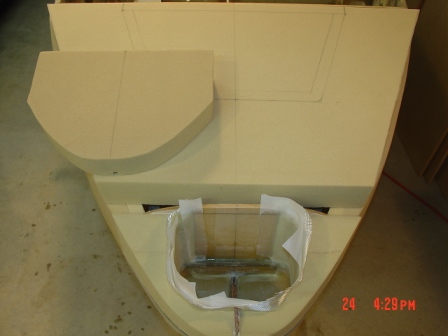
 Foam
blocks build up for nose.
Foam
blocks build up for nose.
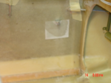
 Inside
shot of wheel well opening.
Inside
shot of wheel well opening.
 The
blue PVC foam is for the rudder pedals mounting hard point and the bottom of
the canard area. Also you can see the pitot and static tubes.
The
blue PVC foam is for the rudder pedals mounting hard point and the bottom of
the canard area. Also you can see the pitot and static tubes.
 Velocity
rubber pedals, I will paint them before final installation.
Velocity
rubber pedals, I will paint them before final installation.
 Opening
on each end is for the canard attachment tabs.
Opening
on each end is for the canard attachment tabs.
 Static
tube floxed in place, marked the outside location to make it easer to drill
the 3 - 1/16th holes.
Static
tube floxed in place, marked the outside location to make it easer to drill
the 3 - 1/16th holes.
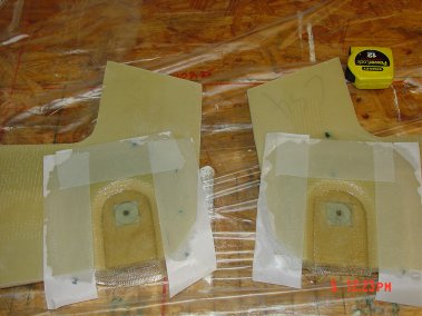
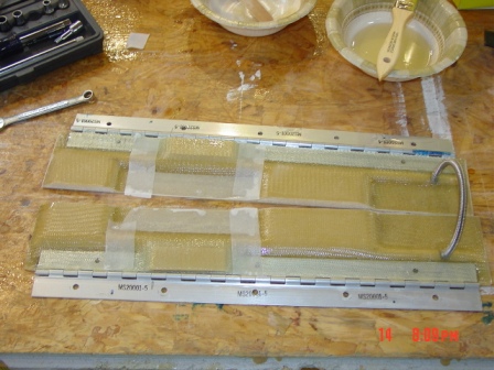
 Made
a cardboard cover that fits the shape of the strut giving enough room for
any movement once installed.
Made
a cardboard cover that fits the shape of the strut giving enough room for
any movement once installed.
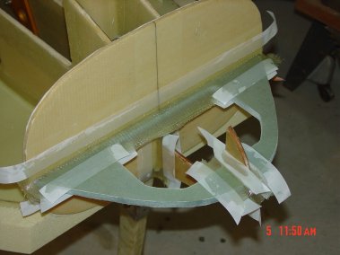
 In
the back you can see the cardboard form and the finished strut cover. To the
left you can see the 1/8" hard board I used to match the cure of the strut.
Packing tape using to cover all allowing release.
In
the back you can see the cardboard form and the finished strut cover. To the
left you can see the 1/8" hard board I used to match the cure of the strut.
Packing tape using to cover all allowing release.
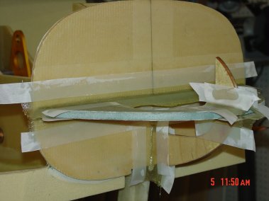
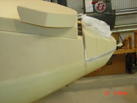
 Strut
cover test fit.
Strut
cover test fit.
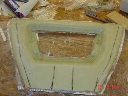
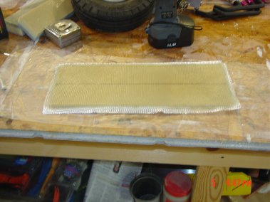
 Wheel
well cover with the foam still inside waiting for the glass to cure.
Wheel
well cover with the foam still inside waiting for the glass to cure.
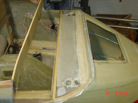
 Window
added to wheel well cover on each side, used to view landing gear position.
Window
added to wheel well cover on each side, used to view landing gear position.
 Started
shaping the sides.
Started
shaping the sides.
 Finished
the side and bottom and floxed in the strut cover, weight down for cure.
Finished
the side and bottom and floxed in the strut cover, weight down for cure.
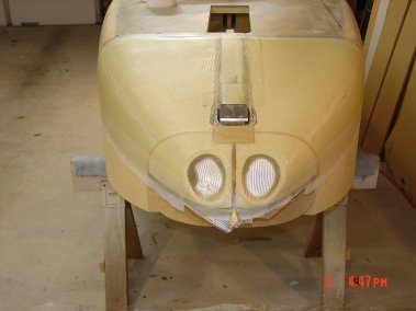
 Finished
landing lights openings, I will use Lexan covers.
Finished
landing lights openings, I will use Lexan covers.
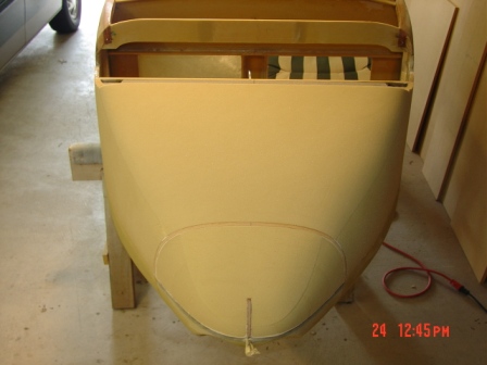
 Glassed
bottom, you can see the pitot tube at the tip of the nose.
Glassed
bottom, you can see the pitot tube at the tip of the nose.
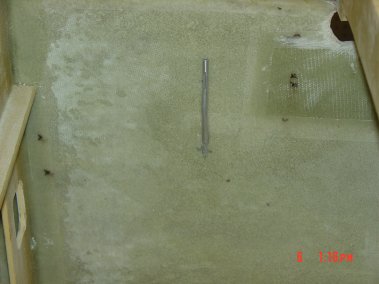
 You
can see that the strut is not yet cut free, waited until glass got to knife
trim stage, then used a steel ruler as a straight edge. Came out real nice.
You
can see that the strut is not yet cut free, waited until glass got to knife
trim stage, then used a steel ruler as a straight edge. Came out real nice.
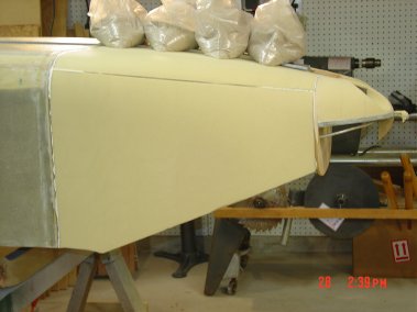
 Nose
foam rough fit, ballast box glassed.
Nose
foam rough fit, ballast box glassed.
 Foam
will be glued in place with 5 min. epoxy temporarily so that it can be
shaped and latter removed to glass the inside.
Foam
will be glued in place with 5 min. epoxy temporarily so that it can be
shaped and latter removed to glass the inside.
 Took
my time with this step using the template created from the drawings,
starting to look good.
Took
my time with this step using the template created from the drawings,
starting to look good.
 Access
doors glassed on nose to get a perfect fit.
Access
doors glassed on nose to get a perfect fit.
 Access
door foam removed, nosed prepped. Glassing inside of doors then put back in
place to cure.
Access
door foam removed, nosed prepped. Glassing inside of doors then put back in
place to cure.
 Glassing
inside of ballast access door. Placed back on nose to cure.
Glassing
inside of ballast access door. Placed back on nose to cure.
 Nose
access door inside glassed, will be placed back on nose to cure.
Nose
access door inside glassed, will be placed back on nose to cure.
 Nosed
is glassed and doors weighted down into recessed openings to cure.
Nosed
is glassed and doors weighted down into recessed openings to cure.
 Used
sand bags to weight down doors during nose glassing.
Used
sand bags to weight down doors during nose glassing.
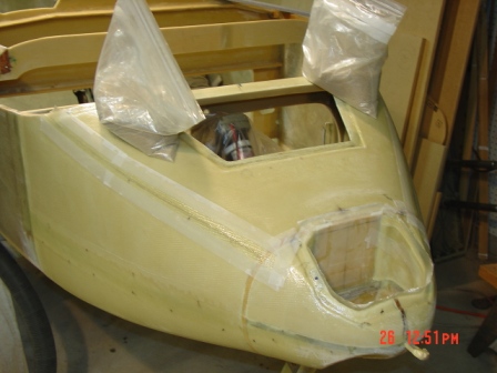
 Nose
top removed to make it easer to work on the rudder peddles and breaks.
Nose
top removed to make it easer to work on the rudder peddles and breaks.
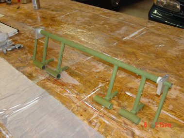
 Brake
cylinder layout, Matco style. I used aluminum square stock to extend
from F0 the mounting brackets are floxed and bid taped in place.
Brake
cylinder layout, Matco style. I used aluminum square stock to extend
from F0 the mounting brackets are floxed and bid taped in place.
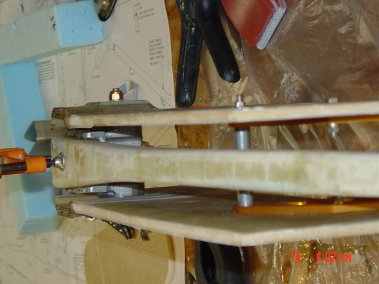
 In
this picture you can see the rudder peddles and the stainless steel forks
that I purchased from Dale Rogers. I first saw this design on Brian DeFords
Cozy. "The actuator is threaded onto the end of the Matco
lay down master cylinder and has a slot wide enough for the rudder pedal to
slide within. A bolt is inserted thru the actuator and thru a hole in the
rudder pedal. As the pedal is compressed the bolt slides in a slot until it
reaches the end of the slot. Once the bolt hits the end of the slot the
master cylinder is then actuated by further pushing on the rudder pedal. The
slot is designed to allow the rudders to be fully deflected at the end of
the slot. The adjustable foot pegs can be seen in this view as well." (Brian
DeFord Web)
In
this picture you can see the rudder peddles and the stainless steel forks
that I purchased from Dale Rogers. I first saw this design on Brian DeFords
Cozy. "The actuator is threaded onto the end of the Matco
lay down master cylinder and has a slot wide enough for the rudder pedal to
slide within. A bolt is inserted thru the actuator and thru a hole in the
rudder pedal. As the pedal is compressed the bolt slides in a slot until it
reaches the end of the slot. Once the bolt hits the end of the slot the
master cylinder is then actuated by further pushing on the rudder pedal. The
slot is designed to allow the rudders to be fully deflected at the end of
the slot. The adjustable foot pegs can be seen in this view as well." (Brian
DeFord Web)
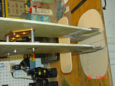
 The
Matco master cylinders are now laying on their sides to make it easer to
connect to the reservoir.
The
Matco master cylinders are now laying on their sides to make it easer to
connect to the reservoir.
 With
this set up I get more than the required peddle travel.
With
this set up I get more than the required peddle travel.
 Glassed
inside top of the nose, the two small foam block in each side of the opening
is where the locking bars for the doors contact.
Glassed
inside top of the nose, the two small foam block in each side of the opening
is where the locking bars for the doors contact.
 Nose
re-attached with flox and bid tape inside and out.
Nose
re-attached with flox and bid tape inside and out.
 Glassed
the canard nose area with two ply of bid and flox corners all around. The
dark green spots are the rudder peddle hard points.
Glassed
the canard nose area with two ply of bid and flox corners all around. The
dark green spots are the rudder peddle hard points.
 I
wanted to lock the nose access door rather then using screws as called for
in the plans, here is what I came up with, works good.
I
wanted to lock the nose access door rather then using screws as called for
in the plans, here is what I came up with, works good.
 Purchased
two keyed alike barrel locks one for the nose and the second on will be used
to open the cockpit.
Purchased
two keyed alike barrel locks one for the nose and the second on will be used
to open the cockpit.
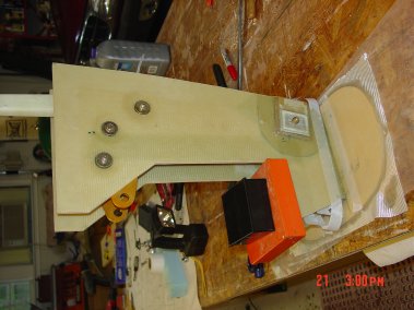
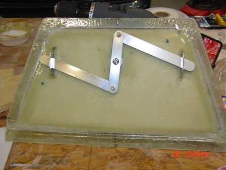
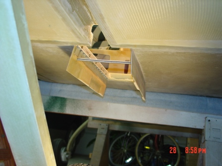
 Here
is the locking mechanism I created for the main nose access door, showing
the locked position. The aluminum bar extend to catch the underside of the
nose compartment.
Here
is the locking mechanism I created for the main nose access door, showing
the locked position. The aluminum bar extend to catch the underside of the
nose compartment.
 In
this picture the locking mechanism is in the open position, the bars retract
in the 90 degree turn of the key, works real smooth and holds the doors down
nice the tight.
In
this picture the locking mechanism is in the open position, the bars retract
in the 90 degree turn of the key, works real smooth and holds the doors down
nice the tight.
 Landing
gear doors material outside glassed, the center line is where I will cut the
doors apart after installed on the hinges.
Landing
gear doors material outside glassed, the center line is where I will cut the
doors apart after installed on the hinges.
 Nose
wheel doors with hinges glassed, removed excess foam for landing gear wheel
and strut.
Nose
wheel doors with hinges glassed, removed excess foam for landing gear wheel
and strut.
 The
spring on the right hand side is used to close the doors when the landing
gear is retracted, got this idea from other buildings. Thanks
The
spring on the right hand side is used to close the doors when the landing
gear is retracted, got this idea from other buildings. Thanks
 Two
strips of ply wood floxed in place with 5 threaded aluminum slugs on each
side. Ends of door opening floxed and glassed.
Two
strips of ply wood floxed in place with 5 threaded aluminum slugs on each
side. Ends of door opening floxed and glassed.
 Floxed
doors in place weighted down.
Floxed
doors in place weighted down.
 Testing
landing gear doors, the spring works great.
Testing
landing gear doors, the spring works great.
 Wheel
well installed with flox and bid.
Wheel
well installed with flox and bid.
 Return
spring mount for rudder peddle, one on each side.
Return
spring mount for rudder peddle, one on each side.
Finished on to Chap. 16, 17 & 24 want to complete as much of
the interior before it becomes impossible to lay the fuselage on its side.
