Started 5/27/2004 finished 8/29/2004 Total chapter hours
worked :63.5
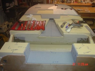
Started by building up foam for the NACA scoop.
Next the plywood and foam for the landing gear and
firewall areas.

Working on the 3/8" PVC foam between the firewall and
landing gear.
 The foam is now ready for contouring. I used a home made sanding board made
out of 3/4 MDF that I sprayed glued 36 grit paper to and the perm-a-grit tool
set about $65 from Wicks.
The foam is now ready for contouring. I used a home made sanding board made
out of 3/4 MDF that I sprayed glued 36 grit paper to and the perm-a-grit tool
set about $65 from Wicks.
Taking your time on this step is key. Work the length front
to back and back to front. This will help you get the feel for how much to
sand and where.
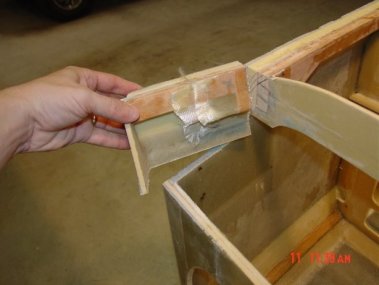
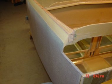
 This picture shows the 1/4" Alum. hard points for the landing gear cover
after they have been floxed in.
This picture shows the 1/4" Alum. hard points for the landing gear cover
after they have been floxed in.
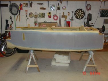
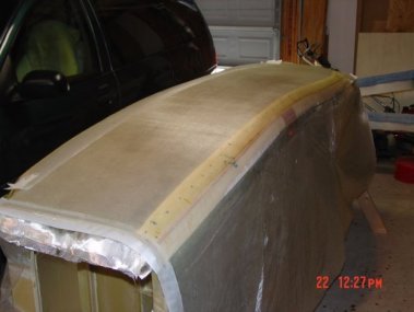
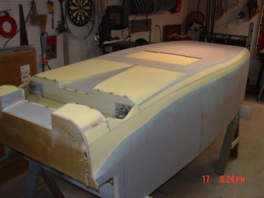 The bottom contouring is complete, here you can see all the contours are
smooth and feathered. You will find that each type of material sands a little
differently, the wood being the hardest along with the macro, that's
where the perma-grit sanding tools make it a lot easer.
The bottom contouring is complete, here you can see all the contours are
smooth and feathered. You will find that each type of material sands a little
differently, the wood being the hardest along with the macro, that's
where the perma-grit sanding tools make it a lot easer.

 Now is the time to build the marker beacon antenna, the materials I
purchased from RST Jim Weir. The co-ax
RG-58 cable is cut into the foam along with the three Ferrite Triodes that
slip over the co-ax and then floxed in place. The copper foil has a sticky
back that hold it in place until the bottom is glassed. Make sure that you
are comfortable with soldering the co-ax to the copper foil, a bad
connection here will make the antenna no good. The co-ax enters in front of
the IP bulk head. Also in these pictures you can see the tape around the air
brake making it possible to have a smooth surface once the final air brake
steps are completed in chapter 9.
Now is the time to build the marker beacon antenna, the materials I
purchased from RST Jim Weir. The co-ax
RG-58 cable is cut into the foam along with the three Ferrite Triodes that
slip over the co-ax and then floxed in place. The copper foil has a sticky
back that hold it in place until the bottom is glassed. Make sure that you
are comfortable with soldering the co-ax to the copper foil, a bad
connection here will make the antenna no good. The co-ax enters in front of
the IP bulk head. Also in these pictures you can see the tape around the air
brake making it possible to have a smooth surface once the final air brake
steps are completed in chapter 9.
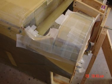
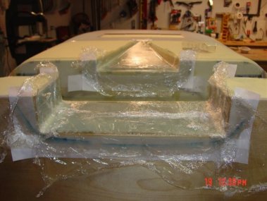 Glassing the NACA scoop is a tough one. The plastic
wrap is there to hold down the glass into the 1/8" joggle for the landing
gear cover. Knife trim flush with the top of the scoop. After cure I carved
out the foam along the scoop top edge, applied flox corners to reinforce the
sharp edge of the NACA scoop.
Glassing the NACA scoop is a tough one. The plastic
wrap is there to hold down the glass into the 1/8" joggle for the landing
gear cover. Knife trim flush with the top of the scoop. After cure I carved
out the foam along the scoop top edge, applied flox corners to reinforce the
sharp edge of the NACA scoop.
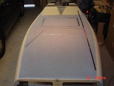
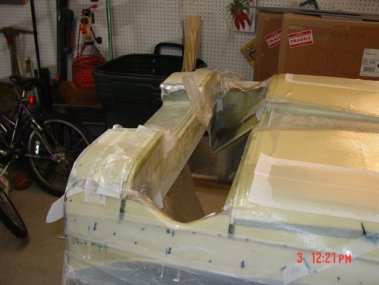
 This picture shows the bottom glassing complete and the air brake. I cut
through some of the glass around the landing brake while the glass was still
curing. This idea I got from other builders web sites, I hope it will make
finishing the brake easer when the time comes.
This picture shows the bottom glassing complete and the air brake. I cut
through some of the glass around the landing brake while the glass was still
curing. This idea I got from other builders web sites, I hope it will make
finishing the brake easer when the time comes.
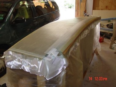
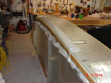
 Here's a picture from the front with the peel & ply still on.
 Engine
and Landing Gear mount reinforcement lay-up.
Engine
and Landing Gear mount reinforcement lay-up.
 These
pictures show some of the engine mount reinforcements on the bottom.
These
pictures show some of the engine mount reinforcements on the bottom.
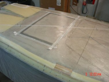
 Here you can see the cut out for the canard, which will be built in
chapters 10,11,12.
Here you can see the cut out for the canard, which will be built in
chapters 10,11,12.
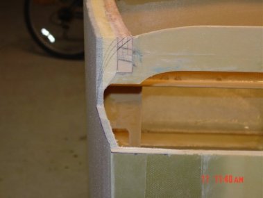 In this shot you can see the template line that I drew to give me an idea as
to how much foam and wood would be removed.
In this shot you can see the template line that I drew to give me an idea as
to how much foam and wood would be removed.
 These three picture show the completed contouring of the top. Just like the
bottom take your time and work the entire length, do NOT try to contour just
one area; like the book says work the length and check with the templates
often. It was very satisfying to see the completed contours come out, not knowing what it
was really going to look like.
These three picture show the completed contouring of the top. Just like the
bottom take your time and work the entire length, do NOT try to contour just
one area; like the book says work the length and check with the templates
often. It was very satisfying to see the completed contours come out, not knowing what it
was really going to look like.

 The fuel sight gage windows will be cover with the fuel sight gages from
Vance Atkinson.
The fuel sight gage windows will be cover with the fuel sight gages from
Vance Atkinson.


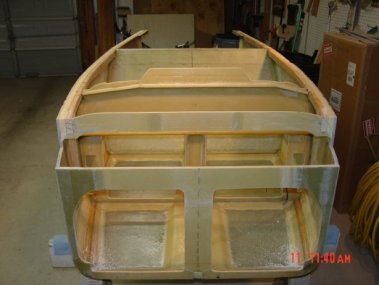
 These five pictures show
the two sides being glassed with there reinforcements. I built two three
legged support systems that allowed me to rotate the fuselage along the
longitudinal axes. To keep the finished bottom and the inside clean I cut garbage bags bottoms off and made long sheets
to protect the other parts, cheep and worked really nicely.
These five pictures show
the two sides being glassed with there reinforcements. I built two three
legged support systems that allowed me to rotate the fuselage along the
longitudinal axes. To keep the finished bottom and the inside clean I cut garbage bags bottoms off and made long sheets
to protect the other parts, cheep and worked really nicely.

 During the process of glassing the side you also have to added the engine
mount reinforcing lay-ups of 3 plies of UND and 2 plies of BID all of which
gets peel & plied.
During the process of glassing the side you also have to added the engine
mount reinforcing lay-ups of 3 plies of UND and 2 plies of BID all of which
gets peel & plied.
On to Chapter 8.
