Started 10/01/2011 finished xx/xx/xxxx Hours worked this
chapter :695 and counting
I've got the engine mount from CG Products
2013 - Going to make the
BIG purchase - Aerosportpower
is my choice IO-375-B1B
I'm going to have an MT constant speed
prop too. This is I think the best choice as the Cozy is a very hard plane
to slow down.
Got the Engine from
Aerosportpower they've been great.

Here she is ready to go. Got all logs showing build
and test ran for 12 hours dyno tuned.

Yes it's all there, 205HP ready to go.

Got the Engine IO375B1B 205hp

Love the blue


Getting ready to fit the cowl.

Weighting down the nose getting ready to mount the engine for the first
time.

Getting ready for the big lift, got the come along connected to the ceiling
rafters with I bolts.


Looks so good I can't wait for full power take off....


Engine is in the air.

Stand made as called for in the plans, I added carpet padding, want to keep
the paint in good condition.

Engine landing on the stand

White and blue looks good to me, Test fit of engine mount

There she is, WOW does that change the CG.

Just to make sure I don't have an upset, I put the engine stand under one
wing.

Cowling from Feather Lite more suppliers found on
CozyAircraft home page

Cowling trim and fit test, good clearance around the engine, small amount of
trimming at wing roots.
 Created some support legs to hold bottom cowling in place during test fit
process.
Created some support legs to hold bottom cowling in place during test fit
process.
 Creating Naca scoop for bottom cowl firewall opening.

Top and bottom cowling fitted, ready for next step.
 Creating
the flanges for the cowl connection to the wing root.
Creating
the flanges for the cowl connection to the wing root.
 Inside
picture of the wing root flange connection fabrication process.
Inside
picture of the wing root flange connection fabrication process.
 Top
cowl flange fabrication
Top
cowl flange fabrication
 Left
wing root flange fabrication
Left
wing root flange fabrication
 Firewall
template getting ready for the FIBERFRAX and aluminum heat shield
Firewall
template getting ready for the FIBERFRAX and aluminum heat shield
 I
am using the 732 High temp Multi Purpose Sealant silicone adhesive/sealant.
I used the notched tool to coat the fiberglass, then the aluminum heat
shield making multi layer protection.
I
am using the 732 High temp Multi Purpose Sealant silicone adhesive/sealant.
I used the notched tool to coat the fiberglass, then the aluminum heat
shield making multi layer protection.
FEATURES
• One-component adhesive/sealant
Cures at room temperature when
exposed to moisture in the air
•Acetoxy cure system
• Non-sag, paste consistency
• Easy to apply
• Cures to a tough, flexible rubber
• Good adhesion to many substrates
Stable and flexible from
60°C (76°F) to +180°C (356°F),
with short peaks up to +205°C
(401°F)
•Black version: stable and flexible
from 60°C (-76°F) to+205°C (401°F), with short peaks
up to +230°C (446°F)
• Excellent dielectric properties
• Complies with MIL-A46106A
• Complies with FDA 177.2600
• Available in white, black or clear
 Here
is the completed installation
Here
is the completed installation
 Second
shot show the protective plastic still on the aluminum heat shield, waiting
for cure.
Second
shot show the protective plastic still on the aluminum heat shield, waiting
for cure.
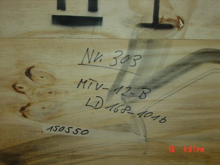 My
MT prop shipping container was delivered on Aug. 2015 can't wait to get the
prop on the engine.
My
MT prop shipping container was delivered on Aug. 2015 can't wait to get the
prop on the engine.
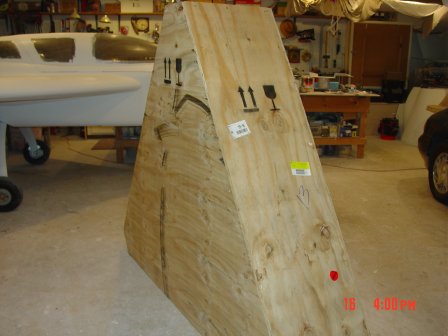 I
tell you one thing the Germans make better shipping container then some
furniture I've owned.
I
tell you one thing the Germans make better shipping container then some
furniture I've owned.
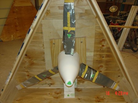
 Here
she is 68" constantans speed in gray so the engine exhaust doesn't show
as much as it would on white.
Here
she is 68" constantans speed in gray so the engine exhaust doesn't show
as much as it would on white.
 With
the nose cone on, the governor is in the box just below the spinner in this
picture, the engine is set up with the mount for this configuration. The way
I looked at it was, giving me a transmission options when in high altitude
operations. As most people know it takes a lot to slow the Cozy down for
landing.
With
the nose cone on, the governor is in the box just below the spinner in this
picture, the engine is set up with the mount for this configuration. The way
I looked at it was, giving me a transmission options when in high altitude
operations. As most people know it takes a lot to slow the Cozy down for
landing.
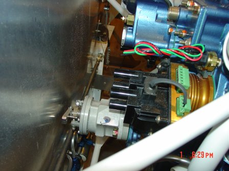 The
second part of the constant speed prop setup is the governor, just enough
room from the firewall. Had to shift the engine 3/4inch back. I don't think
it will impact C/G that much will have to do a check once I get to that
point.
The
second part of the constant speed prop setup is the governor, just enough
room from the firewall. Had to shift the engine 3/4inch back. I don't think
it will impact C/G that much will have to do a check once I get to that
point.
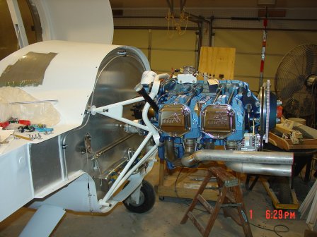 Engine
mounted to the firewall, one step at a time. So cool I can't wait till she's
in the air with me along for the ride of course.
Engine
mounted to the firewall, one step at a time. So cool I can't wait till she's
in the air with me along for the ride of course.
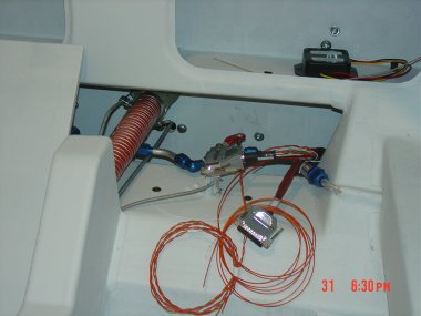
 Building
of fuel boost pump, the pump is on the lower right with pressure recycle
valve loop to tee fitting , filter on left gold color.
Building
of fuel boost pump, the pump is on the lower right with pressure recycle
valve loop to tee fitting , filter on left gold color.
 Mounting
the fuel boost pump as low as possible for two major reasons, below the two
wing tanks, and in the high pressure air stream to keep the fuel cool on hot
Houston days.
Mounting
the fuel boost pump as low as possible for two major reasons, below the two
wing tanks, and in the high pressure air stream to keep the fuel cool on hot
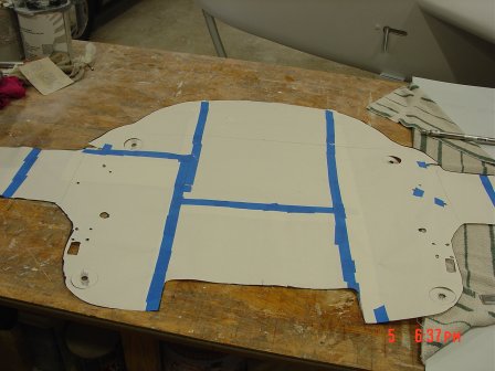
Houston days.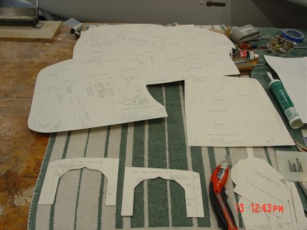 To
make the baffles I started with a tracing of the blue prints from the plans
and spray glued to construction paper to make them stiff enough to test fit.
To
make the baffles I started with a tracing of the blue prints from the plans
and spray glued to construction paper to make them stiff enough to test fit.
 With
the different jug neck on this model engine I had to make templates first as
this it's easer to modify paper and when you've got it fitting correct to then transfer to metal baffles.
With
the different jug neck on this model engine I had to make templates first as
this it's easer to modify paper and when you've got it fitting correct to then transfer to metal baffles.
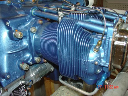
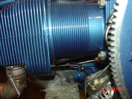 As
you can see here the neck is conical tapper.
As
you can see here the neck is conical tapper.
 This
tapper changed every baffle for the four cylinders necks eight in total.
This
tapper changed every baffle for the four cylinders necks eight in total.
 As
you can see with the blue tape shows where minor adjustments had to be made
as each engine is not the same as the plans baffles.
As
you can see with the blue tape shows where minor adjustments had to be made
as each engine is not the same as the plans baffles.
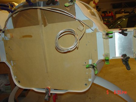
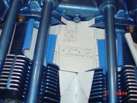 In
this picture you can see the center baffle that had to be adjusted to fit
the conical taper jug necks, this was one of the major reasons I did all the
baffles in paper first.
In
this picture you can see the center baffle that had to be adjusted to fit
the conical taper jug necks, this was one of the major reasons I did all the
baffles in paper first.
 Cylinder
head baffle right
Cylinder
head baffle right

Building the heat duct control valve, working nice with a push pull cable.
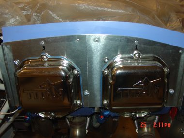
 Same
side with the bolts in place and clips holding the corners.
Same
side with the bolts in place and clips holding the corners.
 This
shows how much tapper is in the neck and the adjustments made on the baffle
templates.
This
shows how much tapper is in the neck and the adjustments made on the baffle
templates.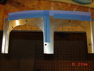
Taped in place to allow rivet work.
High temp. blue silicon rubber baffles, good to 450 deg.

Details show how the spark plug wires go through baffle.
On the right side of the picture you can see how the baffle work with fuel
lines.
Letting the pass through and conforms to the shape give a good seal.
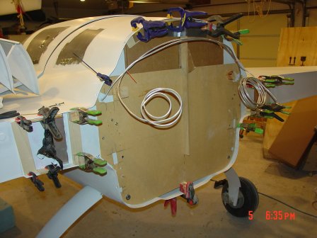
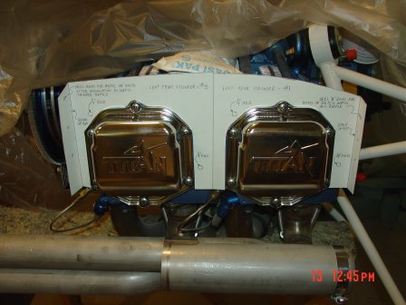
 Like
any other projects you will have many fronts moving forward, in this picture
here is the lower cowl baffles that will direct the NACA high pressure air
up into the engine. Got to keep her cool.
Like
any other projects you will have many fronts moving forward, in this picture
here is the lower cowl baffles that will direct the NACA high pressure air
up into the engine. Got to keep her cool.
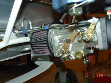
 Moved
the fuel injectors to the top of the engine away from the exhaust pipes
Moved
the fuel injectors to the top of the engine away from the exhaust pipes
 Had
to create a new bracket for the distribution block for the injector lines. I
was not sure how the injection system worked as I've only working with E.F.I.
systems. The way the engineer explained it to me is the fuel is metered at a
constant rate depending on servo control positions into the intake header just
before the intake valves. So there is no injection order to match to the
firing order.
Had
to create a new bracket for the distribution block for the injector lines. I
was not sure how the injection system worked as I've only working with E.F.I.
systems. The way the engineer explained it to me is the fuel is metered at a
constant rate depending on servo control positions into the intake header just
before the intake valves. So there is no injection order to match to the
firing order.
 In
this picture you can see the injector just above the lower intake port and
the head oil return line.
In
this picture you can see the injector just above the lower intake port and
the head oil return line.
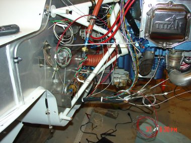
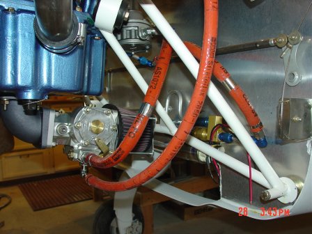 Fuel
lines from fuel boost pump to mechanical engine pump to fuel servo to
injectors. The red cover is fire hose protection for the fuel lines.
Fuel
lines from fuel boost pump to mechanical engine pump to fuel servo to
injectors. The red cover is fire hose protection for the fuel lines.
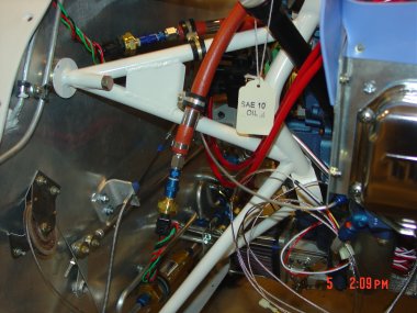
 In
this picture you can see the two fuel lines one from each wing tank sump.
Note the fuel check valves that prevent flow from one tank to the other.
Example if you are flying in a cross wind that may have one wing lower you
can see that high to low would be a problem, hence the check valves to stop
that from happening.
In
this picture you can see the two fuel lines one from each wing tank sump.
Note the fuel check valves that prevent flow from one tank to the other.
Example if you are flying in a cross wind that may have one wing lower you
can see that high to low would be a problem, hence the check valves to stop
that from happening.
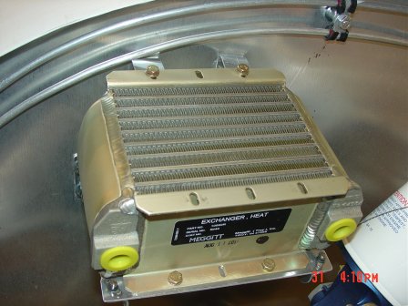 Oil
cooler mounted and rock solid.
Oil
cooler mounted and rock solid.
 Below
the oil cooler you can see the hand made bracket with the wholes to lighten it as much
as possible. Of course made in paper first with some adjustments to get it
right before copied into metal.
Below
the oil cooler you can see the hand made bracket with the wholes to lighten it as much
as possible. Of course made in paper first with some adjustments to get it
right before copied into metal.
 Here
you can see the Aeroquip 666 3/8 lines, with the AE21496-H ends. That
was a long search to find a location that has the hydraulic crimper mandrel
machine. Turned out to be a NAPA auto store that did it for me.
Here
you can see the Aeroquip 666 3/8 lines, with the AE21496-H ends. That
was a long search to find a location that has the hydraulic crimper mandrel
machine. Turned out to be a NAPA auto store that did it for me.
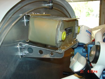
 I'm
going to vent the oil cooler heat out the top cowling so here's the duct
work to do so.
I'm
going to vent the oil cooler heat out the top cowling so here's the duct
work to do so.
 Doesn't
look like much but this is the rough form waiting for the glass to cure.
Doesn't
look like much but this is the rough form waiting for the glass to cure.

Completed Oil cooler duct work sending hot engine air out the top cowling.

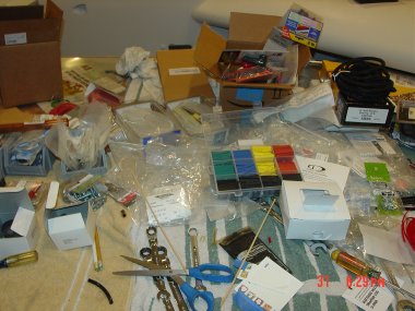
Electrical supplies as you can see I want to make sure all wiring is
protected.
Using mish weave wire sleeves, pass through firewall with brass FW
connection.
Rated to 400 deg.
Color coding the connection make go back to fix an issue that much easer.
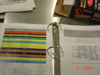
Here is a picture showing the
Dynon
installation book for the (Engine Monitoring System) EMS
The EMS and Fuel level probes computers will be on the inside of the FW.
EMS will be in the lower section and the fuel probes will be in the spar
along with other heat sensitive electronics.

EGT, CHT probes with wiring rough runs. above you can see the heat muff run
for the cabin heat.
Pilot side you can see the MAP tube coming from #3 and the wiring harness
for the EMS probes.
Fuel and Oil pressure probes mounted on line away from engine vibrations.

Right side EGT /CHT probes run with braded stainless line due to high temps.
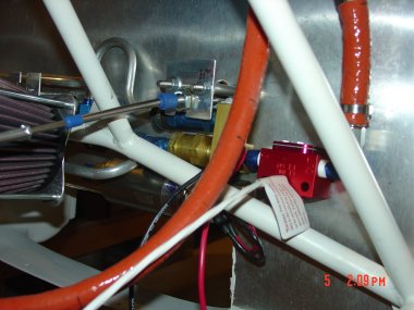
Fuel flow on the discharge side of the boost pump "RED" block.
You can also see the mixture push/pull cable with the plate I added to help
clear the fuel lines.
Fuel servo with the throttle push/pull cable.
More to come Lot's more...
