Last big glassing chapter.
 Fabrication
of parts
Fabrication
of parts
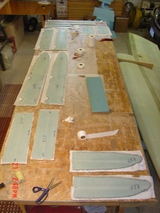
 With
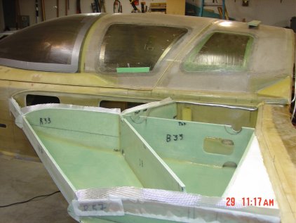
the part all cut out and labeled, glass with peel-n-ply and the orientations
are marked as well. The large number of part and the left and right tanks
having the same part but with different angles it will help during assembly.
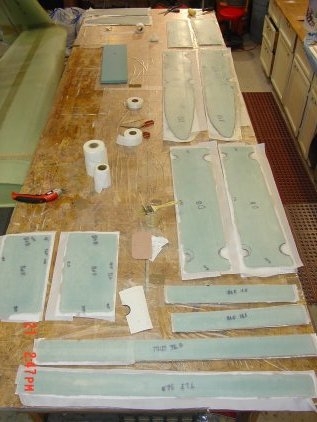
With
the part all cut out and labeled, glass with peel-n-ply and the orientations
are marked as well. The large number of part and the left and right tanks
having the same part but with different angles it will help during assembly.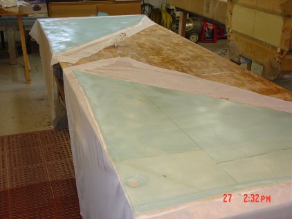 Here's
the bottom skins glassed with peel-n-ply sheet material. In the lower corner
you can see the sump opening.
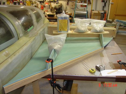
Here's
the bottom skins glassed with peel-n-ply sheet material. In the lower corner
you can see the sump opening.
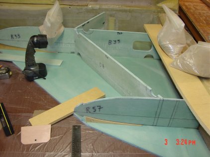 Set
the bottom skin with flox of the back end of the bulkheads (33, 57)to make
sure the are true and fixed before moving forward to the leading edge.
Set
the bottom skin with flox of the back end of the bulkheads (33, 57)to make
sure the are true and fixed before moving forward to the leading edge.
 In
this picture you can see that they other bulkheads are not floxed yet.
In
this picture you can see that they other bulkheads are not floxed yet.
 Now
that the back end of (33, 57) are cured I can bend up the bottom skin
without any concern of the bulkheads moving. Worked great.
Now
that the back end of (33, 57) are cured I can bend up the bottom skin
without any concern of the bulkheads moving. Worked great.
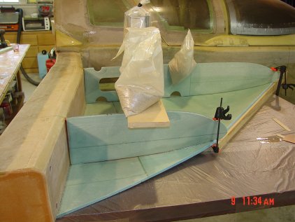 Here
you see the bottom skin and bulkhead 33 & 57 floxed in place. I did this in
stages first I floxed the bottom skin at the spar joint and let it cure,
next floxed the two bulkhead at the spar joint, at the stage you see in the
picture I've put in the jig board and clamped it in place with sand bags to
cure.Co-pilots
side with major bulkhead in place test fit
Here
you see the bottom skin and bulkhead 33 & 57 floxed in place. I did this in
stages first I floxed the bottom skin at the spar joint and let it cure,
next floxed the two bulkhead at the spar joint, at the stage you see in the
picture I've put in the jig board and clamped it in place with sand bags to
cure.Co-pilots
side with major bulkhead in place test fit
 All
bid tap completed second coating of epoxy required to seal inside of fuel
tank.
All
bid tap completed second coating of epoxy required to seal inside of fuel
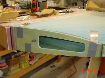
tank.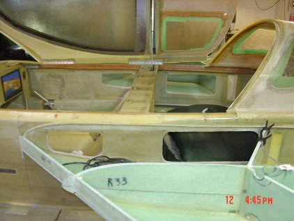 Cutting
rough baggage access openings
Cutting
rough baggage access openings
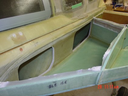 Baggage
openings refined glass support lip on fuselage and added bid tape on the
inside of baggage, epoxy on the bottom part this will be finished when the top
skin is installed. I wanted to make sure I had the bid tap in the correct
location to prevent and leaks into the baggage bay. Worked out just as I hoped
although you have to be limber and take your time. I cut a brush hand off to
make it shorter to fit into the bay.
Baggage
openings refined glass support lip on fuselage and added bid tape on the
inside of baggage, epoxy on the bottom part this will be finished when the top
skin is installed. I wanted to make sure I had the bid tap in the correct
location to prevent and leaks into the baggage bay. Worked out just as I hoped
although you have to be limber and take your time. I cut a brush hand off to
make it shorter to fit into the bay.
 Here
you can see the pour foam that fill the space next tot he spar, this is done
to keep C of G correct.
Here
you can see the pour foam that fill the space next tot he spar, this is done
to keep C of G correct.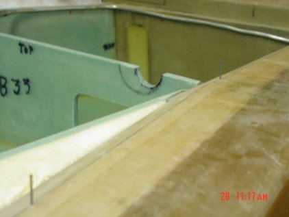 Vent
line is in place and you can see the location nails used to location the top
skin. I wanted to make sure that during the install it did not slide around
and the flox stayed put on all bulkhead and joints are good the sealed.
Vent
line is in place and you can see the location nails used to location the top
skin. I wanted to make sure that during the install it did not slide around
and the flox stayed put on all bulkhead and joints are good the sealed.
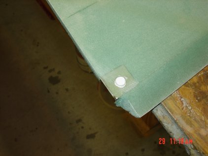
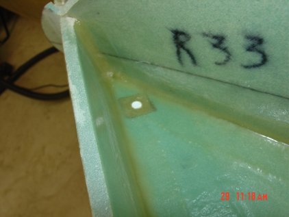 The
white is silicone plug to keep out the epoxy. When ready I just pick out the
plug and the threads are clean and ready for the drain valve.
The
white is silicone plug to keep out the epoxy. When ready I just pick out the
plug and the threads are clean and ready for the drain valve.
 Tea
Bag strainer used to cover the sump opening in the fuel tank
Tea
Bag strainer used to cover the sump opening in the fuel tank
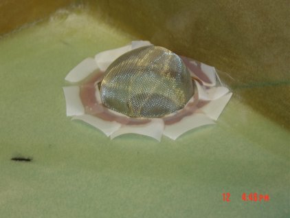 Sanded
the edge of the strainer and floxed it in place.
Sanded
the edge of the strainer and floxed it in place.
 View
of the vent line and sump opening with strainer
View
of the vent line and sump opening with strainer
 Staying
tight to the fuselage hides the vent line exit thought the fire wall.
Staying
tight to the fuselage hides the vent line exit thought the fire wall.
 Sump
fuel line floxed in place before sump addition.
Sump
fuel line floxed in place before sump addition.
 Fuel
sending unit plug.
Fuel
sending unit plug.
 Top
skin floxed in with sand bags and duct tap to hold fast.
Top
skin floxed in with sand bags and duct tap to hold fast.
 OD
bulkhead opening before installation
OD
bulkhead opening before installation
 OD
floxed in place
OD
floxed in place
 I
change the fuel valve set up so that I can control remotely two valves with
push/pull cables
I
change the fuel valve set up so that I can control remotely two valves with
push/pull cables
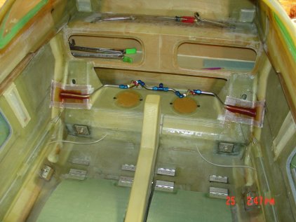 Here's
the valve manifold installed
Here's
the valve manifold installed
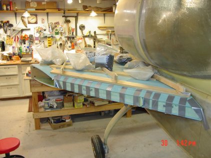
 Block
and tackle set up to flip the airplane
Block
and tackle set up to flip the airplane
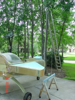 Here
you see a saw horse with office chair caster on so that I can roll the
airplane into my garage once turn over.
Here
you see a saw horse with office chair caster on so that I can roll the
airplane into my garage once turn over.
 Ready
set....
Ready
set....
 GO!
GO!

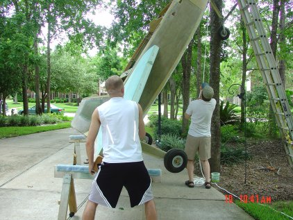 Pull
Pull... Hold her steady boys.
Pull
Pull... Hold her steady boys.
 And
there you go all done.
And
there you go all done.
 Rolled
it in, now set up to do the fairings work and the sump tank.
Rolled
it in, now set up to do the fairings work and the sump tank.
 Glassing
over the foam form for the sump tank left side
Glassing
over the foam form for the sump tank left side
 Same
process on the right sump tank.
Same
process on the right sump tank.
 Pour
foam used to fill in the fairing of the sump tank
Pour
foam used to fill in the fairing of the sump tank
 Sanded
fairing sump tank shown here
Sanded
fairing sump tank shown here
 Glass
the front part and pour form the back section.
Glass
the front part and pour form the back section.
 Removed
the form around the pour foam
Removed
the form around the pour foam

Glassing the top after bottom fairing is finished.
 Leading
edge shaped and glass applied.
Leading
edge shaped and glass applied.

Used a long sanding block to get a true and straight edge before glassing.
 Form
created out of cardboard and packing tape, set to fill with pour foam for
top fairing.
Form
created out of cardboard and packing tape, set to fill with pour foam for
top fairing.
 Pour
foam close-up shot
Pour
foam close-up shot
 Top
fairing glassed look from front
Top
fairing glassed look from front
 Picture
from the firewall end here you can see the fuel vent line.
Picture
from the firewall end here you can see the fuel vent line.
 Used
a glove to see if the pressure would hold over lunch time, just for fun.
Used
a glove to see if the pressure would hold over lunch time, just for fun.
 Here you can see my water column with lots of testing. Found a leak in
the fuel line fitting on the left wing.
Here you can see my water column with lots of testing. Found a leak in
the fuel line fitting on the left wing.
 Keep
track of the barometric pressure and air temp. to make sure the fuel tanks
are air tight. Three tests later all is good after 5 days pressure
test.
Keep
track of the barometric pressure and air temp. to make sure the fuel tanks
are air tight. Three tests later all is good after 5 days pressure
test. Here
you can see the space between the wing root and the fuel strake.
Here
you can see the space between the wing root and the fuel strake.
 Getting
tight in the workshop.
Getting
tight in the workshop.
 Filling
in the space between the wing root and the angled fuel strake left side
Filling
in the space between the wing root and the angled fuel strake left side
 Same
for the right side, here you can see the wood spacers used to keep the
alignment correct and the spacing.
Same
for the right side, here you can see the wood spacers used to keep the
alignment correct and the spacing.

