Cozy Home | Project Status |
Chapter - 4 5 6 7 8 9 10 11 12 13 14 15 16 17 18 19 20 21 22 23 24 25 26
| CHAPTER 21 - Strakes (Fuel Tanks and "Baggage" Compartment) | |
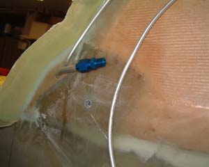
This is the final structural component!!!! I guess if I really wanted to I could throw an engine on and take it up for a spin after I finish this chapter! NOT! I decided to install capacitant fuel probes to have yet another means of monitoring fuels levels. The second leading cause of general aviation airplane accidents is related to fuel management. So, having lots of measuring is a good thing - well I guess if you pay attention to it anyway! To see my installation of the fuel probes - click here. |
|
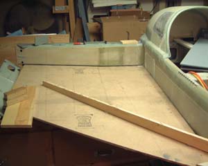 |
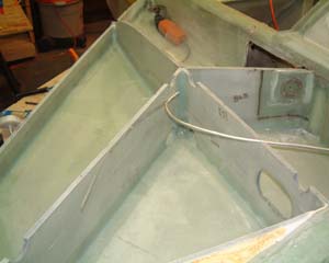
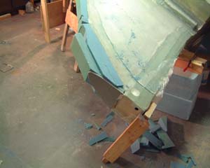
The strake building actually starts with cutting out and glassing the individual ribs and bulkheads that go in the fuel tank and baggage area. I didn't take a picture of that, so you get to start with the "Strake Table". This table is built underneath where the strakes will go and is setup level fore and aft and it slants up with the slant of the center spar. The diagonal wood rail is cut so that the forward edge of the bottom strake foam rests on top of this rail. That causes the bottom to gently curve up in the front. After the bottom foam is glassed it is slit at 1" intervals along the forward edge to help it curve. However I discovered that the foam curves too well after it is slit. It had a tendency to droop below the ribs. So I added some additional bracing after I had the ribs in place and could tell how high the bracing needed to be to support the strake bottom without lifting the ribs off the front rail. |
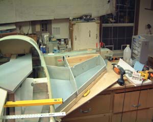 |
I'm positioning the ribs in place to adjust fit and get everything at the right elevation and position. |
 |
I'm doing both strakes at the same time - makes it easier to remember the "lessons" (read "mistakes") from one side to the other. |
 |
Here I've finished floxing and glassing in the strake ribs and bulkheads. It doesn't look like a lot of work but there are a bizzilion junctions between ribs and other ribs and the strake bottom and the fuselage and the center spar...... It was a lot more work than I had counted on to flox and glass all those seams. I was extra extra extra careful to make sure I got a good solid bead of flox in all the corners and a good wet layup on the seam tape. I don't want any leaks!!! |
 |
I ran the vent line in the "plans" way - which is to say the plans aren't
real specific so it follows the plans as much as the plans say. I did add a couple of items to the
vent lines. First I added an narrow aluminum strip that can later be attached to the gas filler
rim.
It is often assumed incorrectly that one wants to electrically ground the gasoline to prevent a static buildup and potential arc and explosion. How do I know it's assumed - because I did! However, I've since learned that gasoline itself is NON-conductive - i.e. you can't ground it because it doesn't carry or transmit an electrical charge. So where's the static - in all the surfaces that the gasoline rubs against. Also all the flying surfaces that air rubs against - i.e. the wings surrounding the gas tanks. So what we're really trying to do is make the metal filler neck at the same electrical potential as the gasoline pump nozzle that's going to touch our filler neck. |
 |
The proper procedure for filling an airplane is to first connect a ground wire to the airplane's exhaust or other part that will be connected via a metal airframe to the gas cap opening. In our birds there is no metal connection to the gas cap opening. So I decided to connect the gas cap filler neck to my vent line and then to my engine block - and hence to my entire electrical system. That way I can ground the connections at either my exhaust or provide a grounding knob by the step on the side of the airplane. |
 |
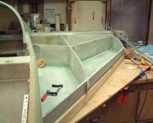
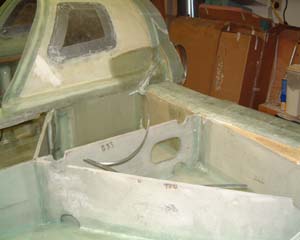
After ribs and ventline are in it's time to put a lid on it! So here's the top. |
 |
DOH! I meant after ribs, ventline, and FUEL RETURN line put the top on!!! So I made another of a long line of mistakes - easily fixed. I carefully used my dremel and a sanding wheel to make a 1/2" hole in foam and fiberglass - while holding the shop vacume about 1 inch from the dremel. Then I floxed in a 3/8" fuel return line. |
 |
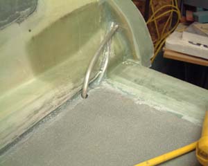
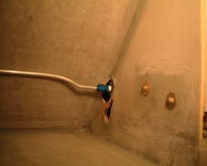
The fuel return line follows the same course as the vent line through the "cosmetic"
piece of the firewall. There it makes a 90 degree turn and is terminated with a flared fitting.
When it comes time to plumb the fuel to the engine I'll put a return line from the fuel injection rail to a tee and from the tee to each tank. The return fuel can go which ever way it wants to. This approach to "tee'ing" the fuel injector return has several
advantages: No, fuel won't be forced up the vent line and out of the tank. The return lines are lower than the vent lines and there will always be a slightly lower - yes, very slight but still lower, pressure in the tank that is being drawn from. |
 |
The fuel line enters the fuselage just ahead of the forward landing gear bulkhead.
I was going to use aluminum welding flanges to connect the fuel tank to the fuel line but decided
it was just as easy to bend a 90 degree into the line and flox it in - as the plans call for.
I cut some wooden strips that were just a little wider than the fuselage and notched on each end. I then bent them slightly and put one end on each fuel line - forcing them against the fuselage wall - but not enough force to dent or deform them. This kept them firmly in place while I floxed and taped them to the fuselage wall. |
 |
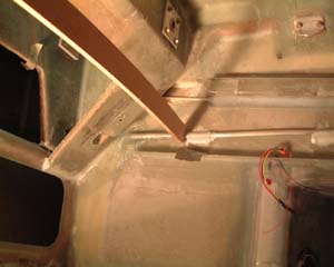
There was no way I could get my fuel valve in with the fuel line connected that runs to the engine. I tried everything and then concluded that I would have to cut way too much off the bracket and brace to make it worthwhile. A better solution was to cut an access hole in one of the side braces so I could attach the flared fitting while the valve was screwed in place. Also, because I'm not using the manual landing brake mechanism - the birch plywood inserts that I cut into are not critical. So here is the notch (under the fuel line) that allows me to attach the fuel line that runs to the engine. |
 |
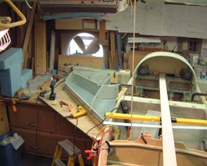
This is where the fuel line turns to go across the seatback. Note that I already have my aileron torque tube in place. Doing the controls chapter (16) before doing the strakes is definitely the way to go since you can easily route the fuel line around things. |
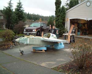 |
The only way to finish the bottom of the strakes is to "flip the bird". To here I am (holding the camera) taking a picture of my flipping crew - my son Andrew. The plane is not as lite as it once was and it was a bear but Andrew and I, with a little help from my wife, were able to muscle it over. |
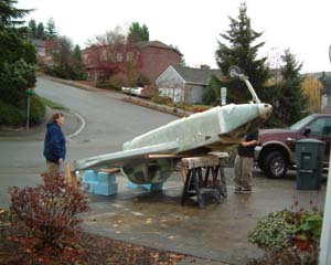 |
I am definitely getting more help when I flip it back topside! But that won't happen until I get the bottom completely finished and painted - as well as the bottom cowling built. Note the sunny day in Seattle!! |
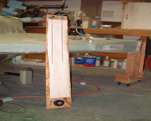 |
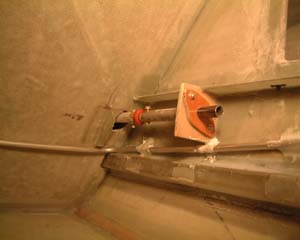
Since I don't have an altimeter yet I had to use another mechanism to pressure test the tanks.
With the help of several suggestions from the Cozy email forum I made a simple water manometer. This is it.
One end of this tube is connected to a Tee which is connected to a valve and the fuel tank. The tube has
about 36" of water in it - 18" on each side when the presure is equal on both sides. I pumped air through
the valve (a simple bathroom water supply valve) into the tee that connects the manometer and the tank.
As the presure builds it forces the water down the high pressure tube and up the neutral tube. 13.6" of
distance up the neutral tube equals 1000ft of altitude - so I presurized to roughly 19.5". Did it stay there - NO!
But it went up then down then up - all dependent on the temperature of the garage and the strakes -
I.e. I could really make it go up by putting a flood light on the strake for an hour!!
All in all it held pressure for more than 24 hours - so I guess I'm good to go! NO LEAKS - YAY!! I was extremely careful in making sure I got a good consistent bead of fairly wet flox in every joint. I also put an extra layer of UNI in several of the fuel bays as added insurance. I figured the UNI layup would be a lot lighter than something like Jeffco sealant - and a lot cheaper! I also had anticipated using the "top hat" technique of building a flange at the top of the ribs and bulkheads - but decided to stick with the plans technique and just "mound up flox". This seemed to work pretty well. |
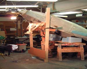 |
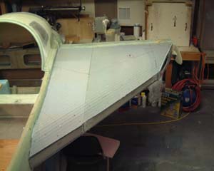
In order to do the leading edge fairings you ideally want to stand the bird on its end so the leading edges are facing up. I, unfortunately, don't have the height in my garage for that (well especially not when I've got 6 flourescent fixtures, 2 airplane wings, and a canard all hanging up there)! So, I got the front up as high as I could and built a stand - then threw some saw horses under just for good measure. |
 |
Here I've got urethane foam glued to the leading edges and in the gap between strakes and wing. Note the dark foam on the end in the shape of the wing. That was put there when I mounted the wings to the center spare. They are bondo'ed to the center spar in the exact position of the wing. The strakes were built to that contour - and then checked after putting the strake tops and bottoms on against the wings. So, to fill in the gap between strakes and wing all I had to do was fill in urethane foam out to that PVC foam piece and then glass over the whole thing. |
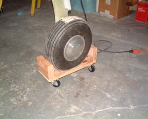 |
Oh, by the way, if you only have a garage to work in it is really essential to make one of these for each wheel. This little wheel dolly allows me to move the airplane any direction I need to. So I can spin the airplane in place - which is about all the room I have anyway! |
| Top - Now on to Chapter 23 - Engine and Cowling. | |