Cozy Home | Project Status |
Chapter - 4 5 6 7 8 9 10 11 12 13 14 15 16 17 18 19 20 21 22 23 24 25 26
| CHAPTER 13 - NOSE & FRONT LANDING GEAR | |
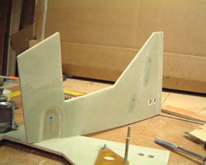 |
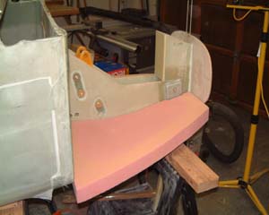
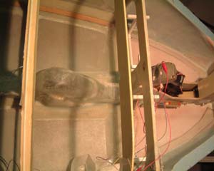
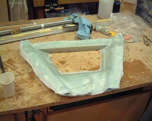
These are the NG30 sides that hold the nose gear pivot and the nose gear raise and lowering mechanism. The 2 holes on the far end are where the rudder pedals pass through. |
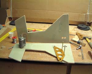 |
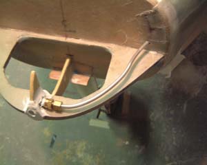
On the left in front of the NG30 is the NG6(?) pivot. The alodined aluminum part on the right side of the NG30 is one of the brackets for Jack Wilhelmson's electric nose lift. |
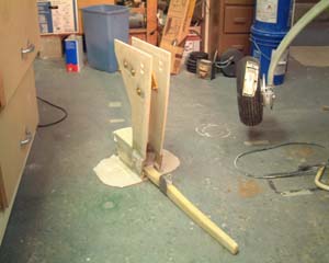 |
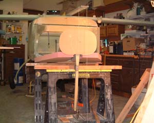
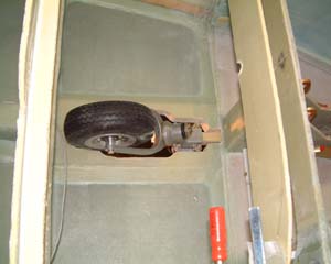
The assembled NG30's, pivot, nose strut, FS-0 bulk head, etc. This is much easier to build on the bench and then mount on the fuselage. |
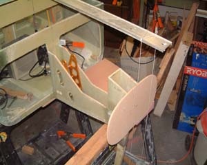 |
Here we are mounting the front LG assembly onto the fuselage. Note the straight-edge on top of the fuselage on the centerline and the plumbline hanging in front of FS-0. This ensures that the landing gear is vertical (assuming the fuselage is leveled side-to-side!). |
 |
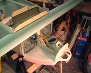
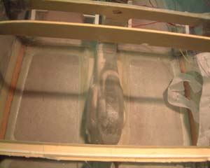
Next comes shaping and micro'ing the nose floor in. |
 |
Still keep that plumb line handy. When putting in the nose floor it's easy to bend the nose a little one way or t'other. |
 |
Looks like some kind of bug! |
 |
Nose sides are contoured from urethane and micro'ed in place. I'm also starting to work on rudder pedals. These are pedals from Dennis Oelman - look good and seem to be very well made. |
 |
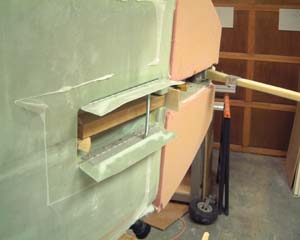
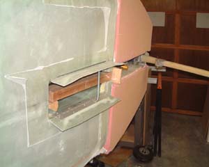
Now it's time to make a place for the retracted front-gear. A hole is cut in the floor between FS22 and the instrument panel that is just a 1/4" larger than any part of the gear that comes into the hole. Not sure why that is - I'm putting doors on so maybe this was a little unnecessary; I.e I could have made the hole a little larger! |
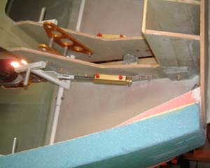 |
Here is a shot of the brakes cylinders attached to the pedals and to NG30. I haven't got the reservoir yet but I think I will go with the kind that attaches directly to the brake cylinders. |
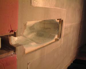 |
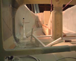
I have created an inside "wheel-house" for the retracted gear. I made a form out of styrene and then covered it with 3 layers of BID. The flat, square opening on either side is where the plywood hardpoints go for the hinge attachment for the gear doors. |
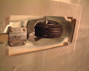 |
Good news - Bad news. Everthing fits perfectly - then I notice that my tire isn't exactly the same size as the full-size drawings. Hmmmm - Aircraft Spruce sent me a 9" tire instead of a 10" tire. And, I've built everything to accomodate the 9" tire....GRRRRRR. Oh well, Aircraft Spruce sent me another tire and a little cutting and epoxy and all is well. |
 |
Here is the inside shot of the "Wheel-house". |
 |
|
 |
Here are the completed gear doors. I fabricated the doors out of 3 ply BID layed into a contoured foam mold. (The gear doors have a 3/8" hump to clear the wheel. |
 |
The spring in the center of the doors pulls the doors closed when the gear is retracted. |
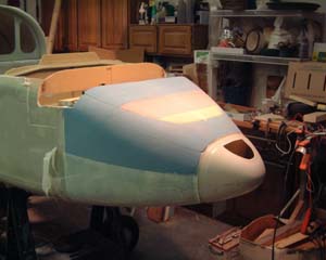 |
After a pause while I built the wings & winglets I'm back working on the nose - why? Because I wanted to carve the nose at the same time as the canopy top. Here I have glassed the bottom of the nose and have carved the top to basic shape. |
 |
Woops - did the foam change color or what? No, I sanded the multi-colored nose pictured above just a hair too low. I tried salvaging it by micro-ing a thin sheet of urethane foam on top - but it wasn't turning out well. So I cut it off and put on a new sheet of urethane foam and here is the final version before glassing. Note that I have the canopy top glassed already. |
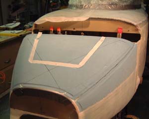 |
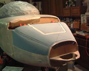
I decided to try doing the nose door a little different than the plans. I have routed out the entire indent for the nose door and put peel-ply around the perimeter. I then glassed the nose - including the indent. I also separately layed-up 4 BID on 4-mil plastic the exact shape of the door. I laid a sheet of 4-mil plastic down and then put the door into the indent to cure. After cure I'll lift off the door and cut the hole for the door - leaving a 5/8" lip. Since I have peel-ply under the lip I will also lay up another couple of plys under the lip for stiffness. |
 |
Here is the nose after it has been glassed. I'm going to leave the nose "unattached" until I'm ready to finish and paint the airplane. It makes it a lot easier to get into the nose to work on brakes, nose retract mechanism, and anything else I put up there while the nose top is off. I may even try to figure out a good way to make the nose top removable. |
 |
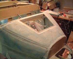
This is the inside of the Nose Top after glassing. |
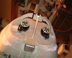 |
I decided to put my landing lights into the nose. The plans call for putting the landing light in a retractable flap under the pilot's seat. Although many who have done it that way say it's a good way to go because you can "aim" you light when landing - others who have put the lights in the nose say it works just fine having them fixed in the nose. Unfortunately I didn't take any pictures of the plexiglass lenses that will be mounted in the nose ahead of the lights. I followed the instructions I found on several web sites and in the archives on how to form plexiglass to a shape. It really was pretty easy. They may not be optically perfect - but they're just fine for landing lights! |
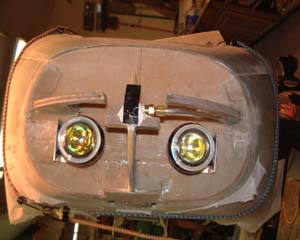 |
Com'in at'cha! |
 |
The landing lights are mounted on aluminum "L" brackets and bolted to the FS-0 bulkhead. |
 |
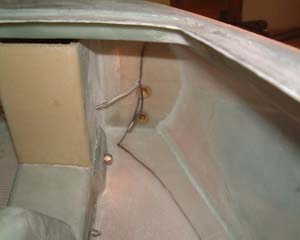
Let's not forget the pitot tube (points into the relative wind and is used to measure airspeed). Notice here that the pitot tube is run on top of the stiffener rib. Now look back a couple of frames at the landing light picture - notice that I've cut the stiffener rib and moved it up above the pitot tube. This was to give a little more room for the lights and to get them a little farther away from the heat of the lights. |
| Top - Now on to Chapter 14 - Center Spar
|
|