Cozy Home | Project Status |
Chapter - 4 5 6 7 8 9 10 11 12 13 14 15 16 17 18 19 20 21 22 23 24 25 26
| CHAPTER 19 - WINGS | ||
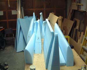 |
My wife and I hot-wired all the foam cores. I took about 2 full days to do. I would setup for a cut and then call her in and we would do the cut. Then she would go back to her sewing while I setup the next cut... | |
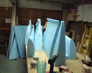 |
All in all they seemed to turn out OK. The first one was pretty miserable. It had lots of craters from too hot a wire. But I'm reasonably certain that enough micro can be found on the open market to fill these canyons! | |
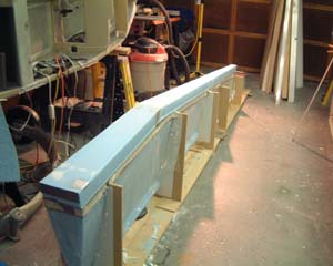 |
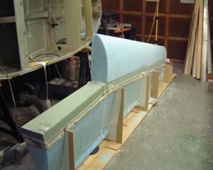
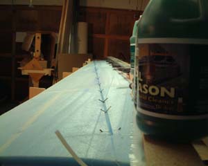
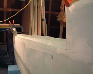
Here the aft half of the right wing is jigged and ready for the spar cap. If you look close you can see the aluminum pieces on the near end and then about 3ft farther down the wing. I jigged the cores up on a platform of 1x8's so I could shim them to compensate for a sloping floor. The jigs are held to the 1x8's with construction angles (about $.19 at the warehouse hardware store of choice). |
|
 |
Notice I had to move the "boat" out of the way so I could get to both sides of the wing to do the shear web layup | |
 |
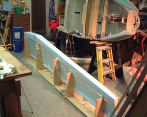
Shear web is done and the front half of the wing is re-united with it's other half. Next step takes it from the floor to the bench for spar caps and layups on bottom and top. | |
 |
The left wing - bottom up - ready for layup (spar cap is already on. | |
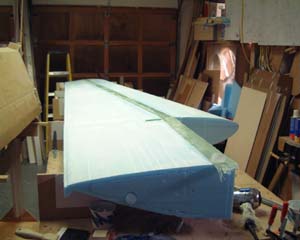 |
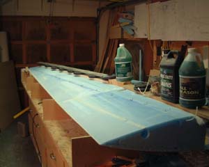
Right wing bottom right after spar cap layup. - Next step is glassing the bottom. | |
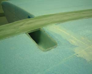 |
Here is a close-up of the wing attach bolt recess. These holes are carved into each side of the wing before the shear web and spar caps are layed up, If you look close there is a little trench around this recess where flox will go prior to glassing the bottom. The flox (cotton fibers and epoxy) provides a solid bond between the fiberglass on the surface and the perpendicular walls of the recess. | |
 |
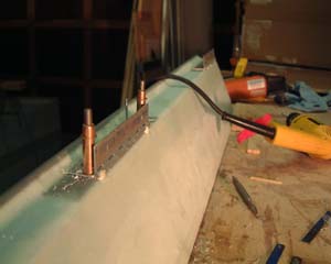
Before glassing the bottom of the wings I installed Jim Weir's copper foil antennae. The wings have Nav antennae and the winglets will have Com antennae. The coax for the antenna runs through a 1/4" hole drilled from the surface at an angle down to the electric conduit that runs parallel with the spar cap. | |
 |
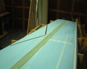
Before glassing the top of the wings one shouldn't forget to put in the rudder cables for the winglets. Here is a shot of the groove and rudder cable (foreground). Note that my groove doesn't curve at the far end. I'm planning on using the "hidden bellhorn's" so the curve isn't necessary. | |
 |
The top spar cap has been layed up and now I'm weighting it down to make sure it is flat (at least anything above the edge). | |
 |
The right wing top is finished. Here I'm removing peel-ply and getting ready to bondo the "level board" on top of the wing. | |
 |
After the top and bottom of the wing are layed up it's time to layup the end ribs. | |
 |
The "Aileron Well" is ready to receive the completed aileron (except for some holes for the hinge screws). | |
 |
To get the hinges in the correct position the plans suggest screwing the hinge to the wing and then using bondo on the side that holds the aileron while setting and positioning the aileron in the wing. So how does one hold the hinge up against the aileron since it is inside the aileron well and inaccessible? Well, lots of people have used rubber ear-plugs or other expandable foam that can push the hinge against the aileron. Another method that I tried and found worked very well was using a cut up hacksaw blade. Yep, you cut a hacksaw blade into 3"-4" lengths and a normal hacksaw blade is just the right width to fit in the slots on the outside of the hinge. So you just slip the pieces in the slot and it pushes the hinge up and holds it there. On the right wing I tried using this Bondo technique to hold the hinges in place while aligning the aileron in the wing slot. It worked marginally. The hinges broke away from the bondo while I was taking the aileron off and because bondo is fairly thick it raised the ailerons just a bit so they weren't aligned just right without the bondo. In the picture on the left - the left wing - I decided to try some 5-minute epoxy mixed with micro and dabbed carefully on the outside edge of the hinge - not underneath. This worked very well! It held the hinges in perfect position and was easy to sand away when done. | |
|
In the Cozy and probably any fixed wing aircraft, it essential to ensure that ailerons and elevators are balanced correctly to avoid "flutter" or "divergent oscillation". Flutter occurs when a control surface has more weight on one side of the pivot point (hinge). I'm no engineer by rely on them and Michael Amick contributed this explaination to the Cozy forum that I found to be helpful. The physics
principle that allows flutter is called divergent oscilation. If the
control surface has more mass aft of the pivot point, it has more enertia
aft of the pivot point, when it moves up or down, or side to side in the rudders
case. If an upward motion were
|
||
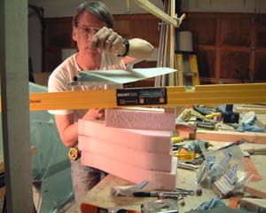 |
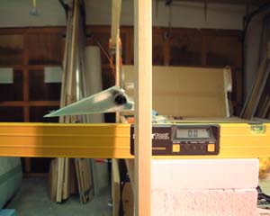
The ailerons have been cut out of the wing and the hinges mounted. Now the moment of truth - are they balanced correctly and not too tail heavy? Looks good! The right wing aileron hangs pointing up 4 degrees. | |
 |
Here the level has been propped up and it reads "4.1 degrees" for the right aileron. | |
 |
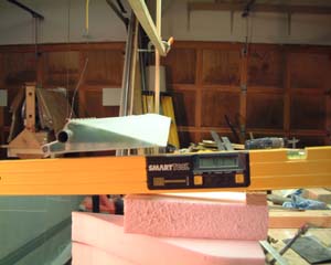
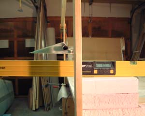
Here we have troubel with the left aileron. The level is level at 0.0 degrees but you see the aileron tilted down about 1 degree. That's bad! So I thought I had somehow made the layup to epoxy rich or used too much micro. | |
 |
So, the plans suggest trying to sand any excess epoxy off and maybe into the top layer of fiberglass just a little. Well I tried that and as you see on the left - with some success. However, 1 degree up will not be enough to compensate for finishing and paint. HMMMMM. Is there something else that could be wrong? | |
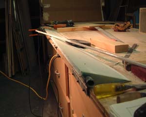 |
It sure is nice to building a plane where you can rip stuff out and re-do it - I'm getting pretty good at it! It dawned on me that balance is not only dependent on the weight on each side of the fulcrum - BUT where you put the fulcrum. So I re-measured everythin and found that I had cut the edge where the steel counter-weight sits a 1/4" short on one end. That put the counter-weight 1/4" closer to the fulcrum (hinge). So (pictured left) I cut out the counter weight and built up the edge with some foam and micro and reinstalled the counter-weight. Bingo! The left aileron was 3.5 degrees up angle. Now I should be able to put some paint on it without putting it below level. | |
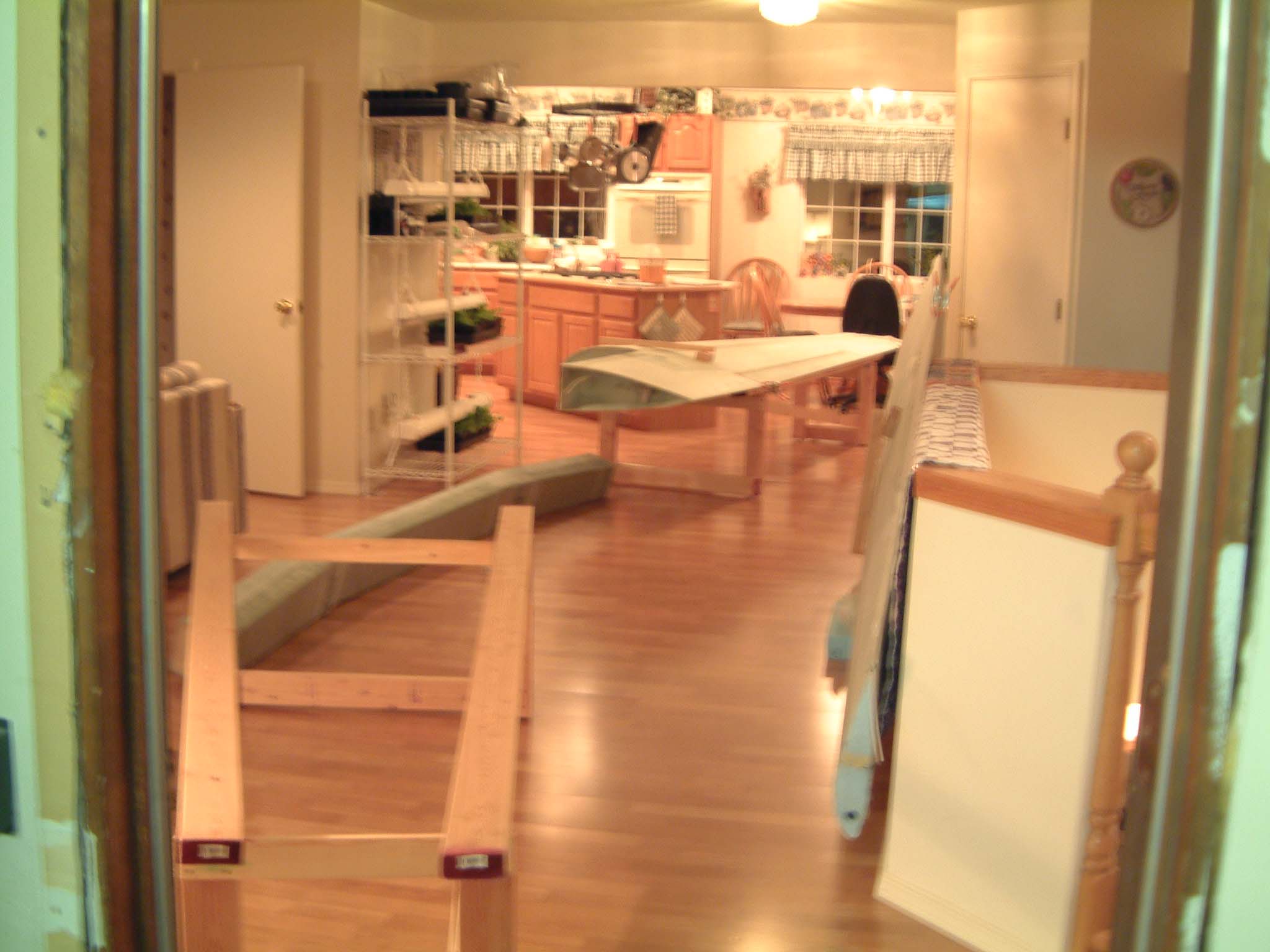 |
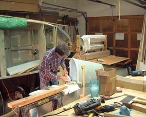
Attaching the wings to the C-Spar is the next and final step in Chapter 19. In Seattle the weather is not conducive to working outside for about 10 months out of the year... so I decided to clear the den and kitchen and lay out the wings indoors. I built some "wing holders" from 2x4's and also a spar | |
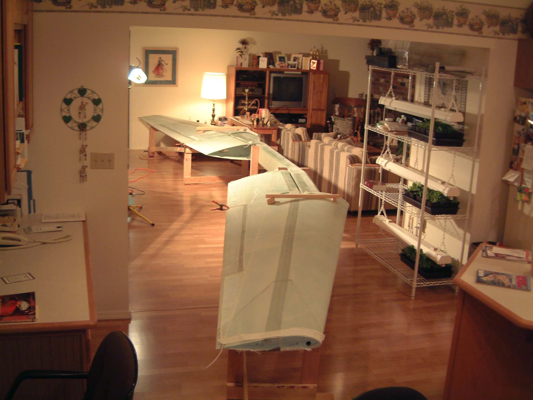 |
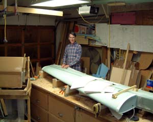
Wings are set in and ready for lots of leveling and drilling. | |
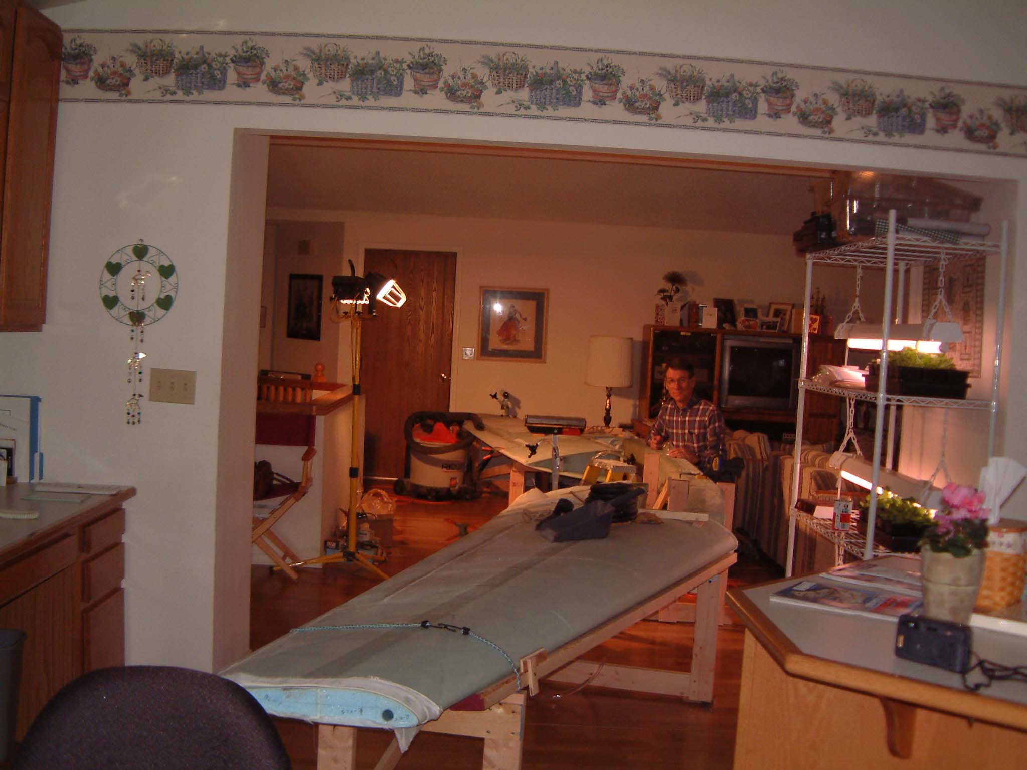 |
Well, what an ordeal! Measure, level, level, level, measure, level, level, drill, drill,..... I spent a good 10 hours at least on Saturday and basically only just got the holes all drilled. I tried the method of drilling a couple of quarter inch holes on either wing then inserting 1/4" bolts, then drilling another couple of holes and inserting 1/4" bolts. Then I drilled the final 2 holes with 1/4" and then immediately with the 5/8" hole-saw. Then inserting 5/8" bolts through those holes and back through the other 4 holes in a similare fashion. The only problem is that when I inserted the 5/8 bolt with a very large washer in the first hole I didn't notice that the washer didn't fit and hit the top of the spar - pushing the spar upward slightly. Oh well, I caught it after only one more hole and went back and adjusted the other hole. All in all I think everything is just about right-on. | |
| Top | ||