Chapter 18: Canopy Lip and Instrument Panel Cover
Step 17: Canopy Lip
The canopy lip was very EZ to complete. I made a slight change to plans. Instead of incorporating the flox corners as shown in Figure 70 on Page 18-12, I applied a 2-BID layup over the exposed foam, overlapping onto the underside of the canopy lip and extending an inch onto the inside skin. Terrible picture, but there's really nothing to it!
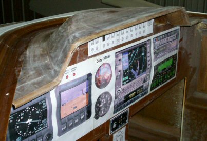
Step 17: Instrument Cover
The plans method of making the IP cover did not appeal to me. Instead, I built the form shown in the picture below and did the shaping and glass work on the workbench, not on the plane. I didn't like attaching the cover with clips either, so I made a recessed joggle under the inside surface of the forward to receive the IP cover.
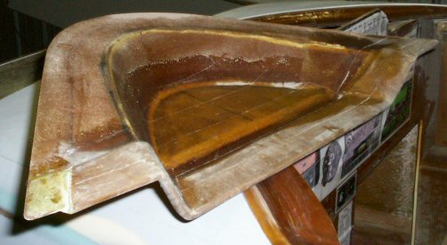
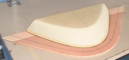
I made the form from left-over strake foam and 2-inch urethane foam. I'm not quite sure how it happened, but the danged thing fit under the canopy on the first try! This will be difficult to explain, but here's how I did it. First, I cut out some left-over strake foam to fit to the shape of the forward deck drip rail, including a 1.5-inch overlap. The overlap is marked by the thin black line in the picture below. I cut out a slot where the IP switch panel would go, taped this "foam base" onto the underside of the forward deck, and positioned the forward deck onto the fuselage. I grabbed a sharpie marker pen, sat in the pilot's seat, and closed the canopy. Holding the pen flat against the inside of the canopy glass, I traced the outline of the canopy onto the foam base. You can see this line at the base of the urethane foam. I next made a paper template of the canopy outline and transferred that to the 2-inch block of urethane foam. That outline gave me the shape of the bottom of the block. I traced the slanted ends of the switch row onto the aft side of the urethane block to give me a guide to work to. Then using the same paper template, I positioned the template on the centerline, slid it backward until the paper template fit between the two slanted marks, and marked out that outline. That gave me the shape of the top of the block. A few minutes of careful cutting with a hacksaw blade and rubbing with a sanding board resulted in the form you see here. Of course, I went through great pains ensuring both halves of the block were symmetrical, and how I did that with paper templates is even harder to explain! Call or write if you really want to know!
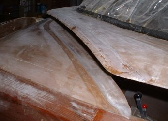
I glassed over the form with 2-BID, and after cure I removed all the foam. I applied box sealant tape to its forward edge (for release), temporarily attached the cover into place, then formed a lower joggle with 2-BID overlapped from the underside of the forward deck onto the cover. I did this instead of using those funky clips.
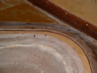
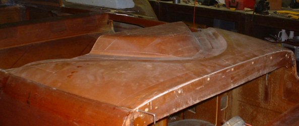
The IP cover is pretty flimsy. I stiffened mine up by added some foam onto the underside of the cover as shown in this picture. Note the "groove" to allow room for the top edge of the instrument panel (switch row).