Chapter 18: Access Door...NOT!
Step 18: Access Door
I've known since Day 1 that I wasn't going to install the access door called out in the plans. While I can stomach the less-than-optimal cosmetics, the door offers no security whatsoever. And many pilots complain that it leaks cold air onto your flying hand. In the rain, it leaks water, too! My solution is to build an actual, user-friendly canopy handle from Lancair IV parts.
Addendum:
Please note that at the time I was designing this latch (2004), the Lancair door parts could be purchased for around $100. Not anymore! They have doubled in price. If I were to do this over again, I'd consider this door latch made by Hendricks Manufacturing .
I'm Doing this Instead (Canopy Latching Handle)
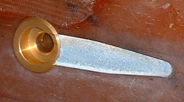
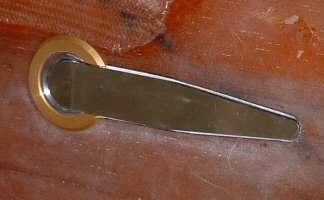
I must have engineered a half-dozen systems before finally settling on one that uses a few hardware pieces from a Lancair IV-P. The Lancair door latching system consists of about 30 pieces of hardware, but I only need 5 -- the collet (gold alodined aluminum collar), the spindle (silver barrel), exterior handle (the pointy chromed steel thing), a roll pin, and a small spring (not shown).
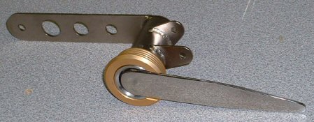
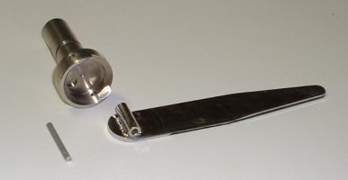
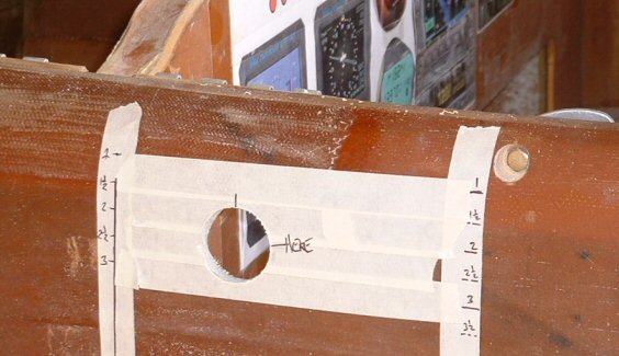
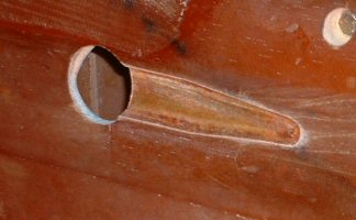
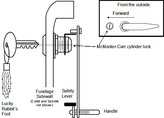
To install the hardware, you drill a 1.5-inch hole into the side of the fuselage just under the upper port longeron. The aluminum collet is floxed and glassed into the hole. I fitting a phenolic collar on the inside of the fuselage to provide more strength for flowing the collet. The chrome handle is attached to the spindle with a small roll pin. A small spring is installed between the spindle and the forward part of the handle to hold it in the recessed position. The spindle is inserted through the collet. The outside handle and spindle are connected to the inside handle with a bolt. The inside handle shown in the first picture is not the one I'm using. It's the one from the Lancair and I show it here for reference only. It doesn't match the geometry I need, so I will fabricate the inside handle shaped like the one shown in the diagrams below. I will also make a tie-rod to connect the inside handle to the forward canopy hook, which was whacked (shortened) for this application. I will also install a cylinder lock that keeps the inside handle from being tampered with.
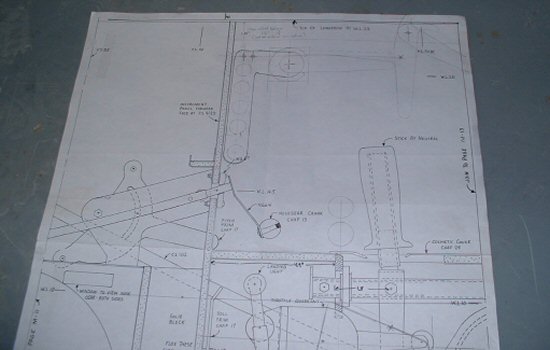
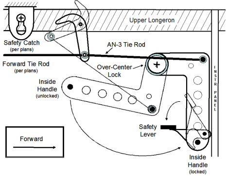
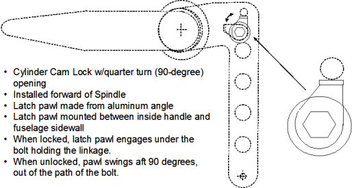
From the diagrams below, it's EZ to see how this system works. To latch the canopy, the pilot rotates the handle into the locked position. A new tie-rod pulls the existing tie rods to close the latch hooks. Just before the final motion, the AN-3 tie rod will move over-center. The forces from the canopy work to always pull the tie-rod in tension, which in turn keeps the handle in its latched position. This is a safety feature I really like. It would take a conscious, positive pull to rotate the handle out of over-center lock. So I'm sure the latch can't be inadvertently opened in flight. Still, I've added a safety catch that you manually swing down to engage the T-bar on the end of the inside handle. I will also install the canopy frame's safety catch shown in the plans. You reverse the process to unlock the canopy. Raise the safety catch, pull the handle out of over-center lock, and continue to rotate open. The latching handle DEFINITELY interferes with the control stick when the canopy is unlatched. So yet another safety feature. I cannot put my hand on the stick without banging into the inside handle. So there's a physical reminder to CHECK CANOPY before takeoff. :-) I will use a quarter turn cam lock to prevent the inside handle from being unlatched.
(Note: At one time I had a drawing posted here that showed a cylinder barrel lock that extended a pin when locked and retracted the pin when unlocked. When locked, the pin extended through a hole in the handle. Well, I must have misinterpreted one of McMaster Carr's diagram because there is no such animal in that catalog. Sorry if I misled some of you....)
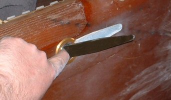
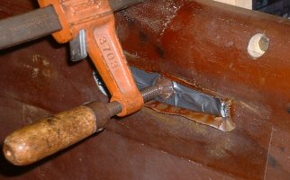
Here are some pictures showing the installation. I spent about 2 hours with the M-drawings to engineer the exact geometry of the inside handle and its location on the fuselage sidewall. I made cardboard templates of the inside handle and verified it all worked. I next transferred the exact hole locations onto the fuselage sidewall, took a deep breath, and drilled the hole. I did a fit-check with the collet, spindle, and outside handle. I carefully traced around the outside handle, routed out the skin and foam so the handle can be recessed into the fuselage side, and glassed 1-BID ply over the recess. I taped the outside handle with duct tape and clamped it into the recess to force the BID to cure in the shape of the handle. One of the pictures below shows how you push on the handle to pop it out for use. I have parts on order for completing the inside handle. I'll post more pictures when the inside handle is installed.