Chapter 16: Canard Controls
Step 4: Installation of Canard Pushrods
Here's the process I used:
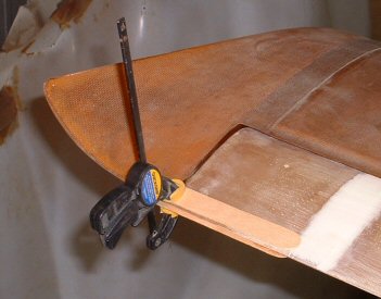
1. Block off the elevators to their zero positions. I did this by clamping the elevators to the wingtips with mixing sticks and clamps.
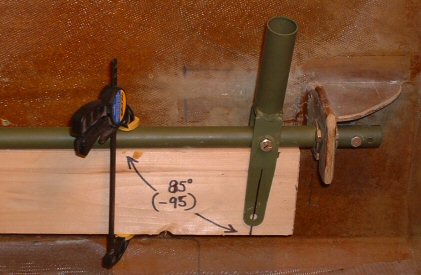
2. Pin the control stick at the 5 degrees forward position. This is easily done by marking out an 85-degree angle on a pine board, clamping the board underneath the torque tubes, and pinning the bottom of the control stick to this angle. With the bottom of the stick at 85 degrees, the control stub is now at 95 degrees, or 5 degrees forward from vertical. Perfect! Now, tighten the AN-4 pivot bolt enough that the control stick won't move from that position. (Or, pin the control handle by placing a drywall screw through the hole in the bottom of the control handle.)
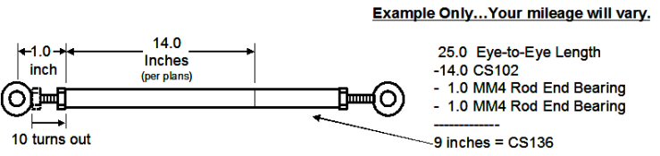
3. Measure the hole-to-hole distance between the hole in the NC12 control arm and the hole in the bottom of the control stick. This yields the custom, eye-to-eye length for the canard push-tube. Use a little math to find the length needed for the CS136 tube. I subtracted the other known measurements from the eye-to-eye measurement. In playing around with the MM4 rod end bearings, I found that tens turns out put the jam nut at about the mid-point, which turned out to be exactly 1 inch. I also assumed the CS1A rod end fitting got inserted fully into the tubes. As you can see, my CS136 tube ended up being 9.0 inches, which is a greater length than the 7 inches specified in Schedule B. Lucky for me I had some extra tubing on hand. Repeat Steps 1 through 3 for the starboard side. I was quite pleased to find that the starboard push-tube was the exact same length. Your mileage may vary.
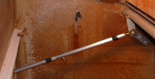
4. Install the push-tubes. This is a picture of the port push-tube. I typically wait to squeeze the rivets until I know everything is working and until after I've painted the parts. So I use black electrical tape to hold the rivets in place so they don't fall out. I took Ken Miller's suggestion and replaced the clevis pin and safety pin with an AN-3 bolt. BTW: Can you spot the error in this picture? The push-tube is mounted incorrectly. It's supposed to be mounted to the outboard side of the NC12 control arm.
5. Cycle the controls through full range of motion and verify no interferences! I had a few interferences. With the sticks full forward (pitch down) and full opposite aileron (top of stick fully inboard), the push-tubes were hitting the bottoms of the CS109 bearing blocks very near the fuselage sidewalls. The tubes were also hitting the tops of the square holes in the instrument panel. (These interferences were there with the plans geometry, even before I had made the bias change in the controls.) So I removed some plywood off the bottom of the CS-109 bearing blocks. raised the height of the hole, and removed some material from the underside of the armrests where it meets the square hole through the instrument panel.
Voila! Now with a flick of the wrist the plane goes up and the plane goes down. Wheeeeee!