Chapter 9: Main Gear Fairings
(Main Gear Fairings are not addressed in the plans.)
The Problems
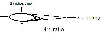
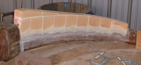
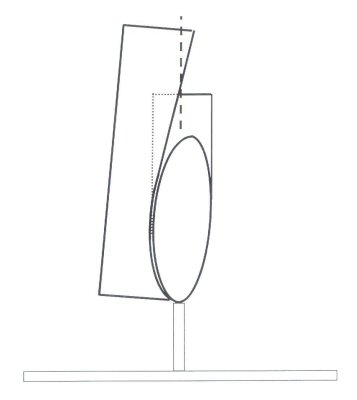
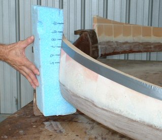
Our gear bows are made in an airfoil shape that should help to reduce drag. But because we install the gear bow at a canted angle to the fuselage, a large majority of each gear leg ends up being set at a positive incidence angle relative to the oncoming airflow. This creates drag. The drag gets worse when we add the brake conduits and extend the trailing edges. Look at your gear bow carefully and you'll see that most of trailing edge is not in trail with the leading edge. If you look at the picture of my gear bow, you can clearly see that the trailing edge is much closer to the square on the right than it is to being mid-way between the two. (The mid-point is about where that shadow line is on the mounting tab.) To help you visualize it, the gear is 2 inches thick at this point. The trailing edge is at 1.625 inches. It should be at 1 inch. It's over a half an inch off from being in trail with the leading edge! And that's after purposely offsetting it to what I thought was higher in the previous steps! Those of you who made your trailing edge in line with the rest of the bow will be even farther off from parallel. Your trailing edge would probably be in line with the square on the right! What a drag, man!


The other problem is that the chord line is not long enough. The speed gurus say that the chord line for an airfoil should be about 4 times its thickness. So the goal is to stack foam blocks onto the gear so we can reshape the legs into an airfoil with a chord line 4 times longer than the section is thick, and to position the trailing edge in trail with the leading edge so that the incidence angle is parallel to the oncoming airflow. It's been said that a "perfectly faired main gear" can gain you about 7-10 knots of airspeed. I intend to gain that with the approach outlined below. Mucho thanx to Ron Springer who inspired this particular approach. The fairings are easier to build if you can take the gear out of the plane.

The Process
Step 1 -- At cruise speeds, our planes fly about 2 degrees nose up. So, jack the plane off the ground so that there’s no weight on the main wheels. Raise the nose wheel up until the top longerons are 2 degrees nose up. Then measure the distance of the gear’s leading edge from vertical. I made my measurement at the point where the leading edge goes into the fuselage. For me, that distance was 3.625 inches. Record this measurement and remove the gear from the fuselage.

Step 2 -- Set your gear bow on your table top, leading edge down. Next, make two standoffs that are as tall as that measured in Step 1. Place these under the gear bow at your measurement spots. Again, you do this to approximate the gear's geometry relative to the fuselage. I just happened to have two bricks that were exactly the right height. So I used those. Now, measure the thickness of the gear bow in intervals along each gear leg. This is most easily done by butting two carpenter squares against the gear and measuring the width between the two squares. I measured the thickness every 3 inches. Write them down because the 4:1 ratios of these thicknesses will determine how high to stack the foam.
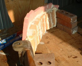
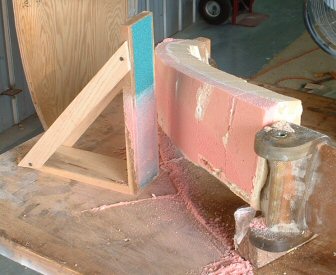
Step 3 -- Now it's time to start piling on the foam. But first things first -- PLUG UP your brake conduits on both ends! Use bolts or golf tees, but use something. You don't want pour foam seeping inside and clogging up the conduits! It's actually easier to pile on the foam with the gear sitting flat on the table. So I removed the bricks and set the gear flush on the table, leading edge down. I attached some of my sticky-back sanding paper to the gear leg. I cut out a urethane foam block, then rubbed the block side to side over the sand paper. This quickly carves the block to the exact shape of the gear leg. After carving two adjacent blocks, I removed the sticky back sand paper, vacuumed up the dust, and laid the blocks side by side, sanded sides up onto wax paper. (The wax paper just catches the pour foam run-offs and helps to keep from pour foaming the top of the table. I also placed wax paper under the gear legs for the same reason.) I mixed up a few ounces of pour foam, then VERY QUICKLY poured the mixture over the blocks, allowing a small portion to dribble into the crack between the two blocks. I VERY QUICKLY took a mixing stick and VERY QUICKLY spread the mixture until the faces of the blocks were covered. I VERY QUICKLY picked up the blocks and positioned them into their proper places on the gear leg. I then pushed a stack of bricks against the blocks to hold them firmly against the gear leg until the pour foam solidified. This process took about 10-15 minutes for each 2-block set. With blocks fitted to the outside and inside of each leg, I trimmed the blocks flush with the trailing edge. For me, it was just easier to glue more blocks onto a flat trailing edge than it was to shape really tall blocks to include the new trailing edge. The first picture is of my gear leg before cutting the foam flush with the trailing edge. The second picture shows the trailing edge blocks glued on (and was taken out of order after completing Step 4, sorry). Now, some people build dams and just pour-foam the entire leg. That's certainly a quick way of doing it. But I loathe pour foam. While quick, pour foam expands and contracts, expands and contracts, expands and contracts.....FOREVER. :-) I didn't want to deal with those issues. I did use pour foam, but only as the "glue" to attach the blocks to the gear legs and to each other. Don’t use micro because (a) it takes too long to wait for cure; and (b) the cured micro will be harder to shape!
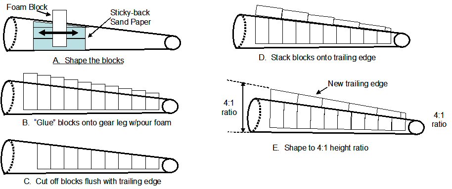

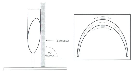
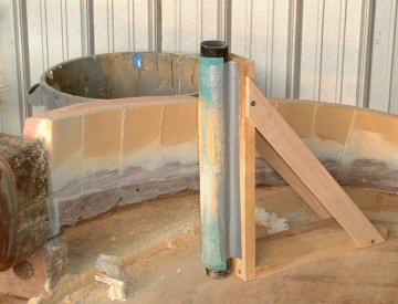
Step 4: -- Make a 90-degree sanding block. I made my sanding block from two pine boards with bracing to hold them perfectly at 90 degrees. Again, raise the bow to achieve the distance measured in Step 1. To keep the bow from moving, secure the bow to the table by screwing in a block of wood at the end of each gear leg. Screw the leg to the block by using a screw through one or two of the axle holes. Now, sand along each side of the bow, removing the foam with each pass until you hit glass. What this does is quickly sets the thickness of the urethane foam blocks to the same thickness of the bow. You MUST do this sanding with the bow raised up to replicate the cant angle to the fuselage (per step 1), or it will not work! As you can see in the pictures, the outside of the bow is sanded with some 40-grit sticky-backed sanding paper stuck onto the flat board. I have just started sanding the outside of the gear bow in the first picture. Now, this configuration won't work for the inside of the bow. Since it is concaved, the edges of the board will grab and gouge the foam. So I attached a large diameter PVC tube to the sanding block. I wrapped the 40 grit sand paper around the tube. In the second picture, you can see how I sanded the inside curve until I "hit the glass". Pretty cool! It only took 30 minutes to sand both sides of one gear leg! I could have done it in 20 minutes, but I was being careful. :-) (Note: The pictures were taken before adding the trailing edge blocks. Sorry. I got impatient and just had to try out the sanding block! :-) )

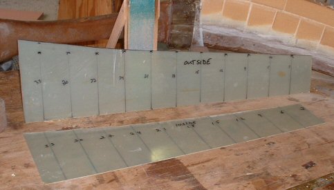
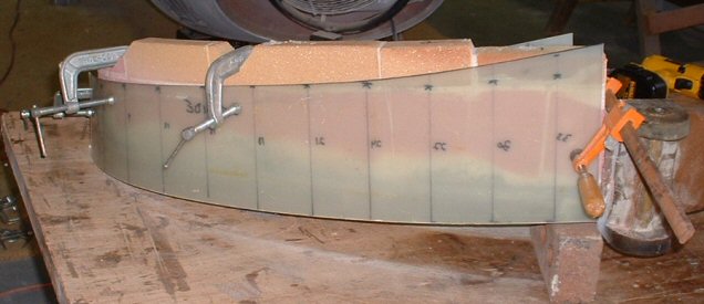
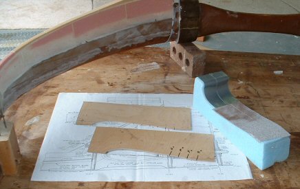
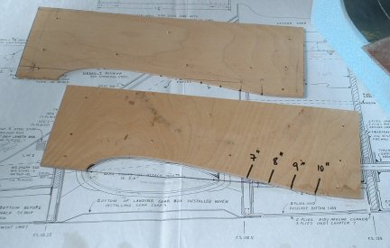
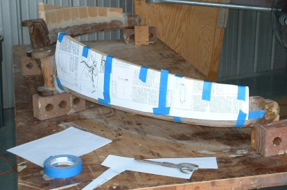
Step 5 -- Now it's time to trim off the trailing edge. Using the thicknesses measured in Step 2, I multiplied them by 4 (4:1 ratio, remember?) and make two templates. I used some plastic sheeting I had lying around. You want something really flexible because you will be bending it around the gear leg. I measured off the 3-inch spacing along the length, then measured up by the 4:1 ratio. When you do this, you'll notice that the marks for the trailing edge will not line up. This is because the gear bows are thicker in some areas than others. The thicknesses are not uniform over the length of the legs either. So, I took a straight edge and made a "best fit." Note that I added a small curve at the fatter part of the template, something approaching a 4.5:1 ratio. I'd like you to think I did that just to make the trailing edge look snarky, but I really did it in anticipation of fitting an intersection fairing later on between the gear legs and the fuselage. Anyway, clamp the two templates onto the gear leg and sand across them to trim the trailing edge to shape.

Step 6 -- Get two 90-degree squares. Now, find the new “centerline” by measuring the width, dividing in half, and marking the spot. Do this about every inch along the length of the bow.
Connect the dots! You’ll have a nice line that is the location of the new trailing edge. Note how your new trailing edge is at a zero incidence angle compared to the angle of the bow's cross section.

Step 7 -- Make yourself an airfoil-shaped sanding block. I had planned to follow Todd Parker's recommendation and use a NACA 16-021 pressure recovery section. Problem is the leading edge portion of the gear's airfoil shape is thinner than the 16-021 profile. I didn't want to mess with adding micro, contouring to shape, THEN glassing. So I just decided to shape an airfoil around the shape of the gear bow. I pulled out the M-drawings and shaped the airfoil you see below. I made two templates, then made the contouring sanding block you see here I applied sticky backed sandpaper onto that portion of the sanding block that touches foam. I applied duct tape to that portion that touches glass. The duct tape allows the sanding block to slide along and keeps the bare glass from abrading the foam sanding block. All I did was hold it in place and sand the foam side to side until I reached the center line. You'll note I have a strip of duct tape at the trailing edge. Once I got to the centerline, I didn't want to sand past it! The duct tape prevents the sandpaper from hitting the foam at that spot. So it prevented me from sanding the trailing edge as I continued to shape and finesse the rest of the foam. After I got the foam contoured, I applied a strip of peel ply onto the foam along the new trailing edge to provide for glass-to-glass bond later. I made a paper template and laid up two 2-UNI layups on the workbench, then transferred the layups onto the gear bow. The 2-UNI layups were on a 30-degree bias like we did on the wings. After cure, I trimmed the trailing edge flush with the foam. I contoured the inside foam and puledl up the peel ply strip from the trailing edge. I applied flox into the trailing edge, slurried the exposed foam, then glassed the inside of the legs with 2-UNI. After cure, I'll trim the trailing edge and the main gear fairings will be completed! I'll then reinstall the gear into the fuselage.

Step 8 -- Once the gear is reset into the fuselage, I'll make some intersection fairing between the gear bow and the fuselage. This is easily done by stacking a small block of foam, carving to a pleasing shape that the oncoming air will like, and glassing BID over it. You can also make the shape from modeling clay and dig it out after.
Pictures of the final product are on the very bottom of the next page.