Chapter 4: Bulkheads

As they say, getting started is half the battle. Although I did some fiberglass work repairing my catamaran (usually as a result of collision due to someone else's stupidity), I felt like a 1st year medical student performing surgery on his first patient. After all, if my fiberglass failed on the boat, all I'd do is sink. If it fails in the air, God would beat the FAA to the crash site. The plans really do become easy to understand once you truly take the time to really read them and correlate the words to the figures.
My bulkhead weights:
|
F22 |
2.09 lbs |
|
F28 |
0.67 lbs |
|
IP |
3.75 lbs |
|
Seatback |
4.86 lbs |
|
FWD LG Upper |
0.70 lbs |
|
FWD LG Lower |
1.32 lbs |
|
AFT LG |
2.52 lbs |
|
Total |
15.9 lbs |
Tips and Suggestions:
1. Do watch the Rutan video on composite construction techniques. It'll save you time and worry. I've never worked with peel-ply before and the video tape helped alot. (Yes--> I peel-plied all bulkheads.)
2. Not wanting to destroy my original M-drawings, I made my paper templates with a Zerox copier. The reverse side was made by placing the M-drawings upside down onto the copy machine and turning the darkness way up. You must be careful when using the Zerox machine as the copied images will distort from parallax -- i.e., the copy will not reproduce exactly like the original. Lines near the edges of the copied paper tend to be longer or shorter than the original. Knowing this, I placed the original M-drawing on my glass-topped end table, shined a workshop light from underneath, lined up the copied pieces over the M-drawing, then taped them into place.
3. I glued the foam edges together using the "hinge" method described on my TIPS Page. I used box tape across the bottom seam, box tape on the top edges of the seam, "bent the hinge" and put the 5-minute glue in the exposed hinge area, then returned the foam flat. I wiped off the glue that oozed out and pulled up the seam edge tapes. As soon as the glue set, I flipped the foam over and removed the seam tape.
4. I used sandwich bags for dispensing flox and 5-minute glue. (See TIPS Page.) Simply mix the stuff, put it into the corner of a sandwich bag, twist off the top opening, and cut the corner off. Use it like a cake icing tool for controlling the flow and coverage of the fluid onto whatever surface.
5. For reference, do draw vertical centerlines on each side of every bulkhead. These reference lines are essential during fuselage assembly and beyond.
6. Don’t be too alarmed when you don’t finish this chapter in the recommended 25 hours. I believe that number is a holdover from the Vari-Eze plans. All the Cozy bulkheads are more than twice as wide, so it should take more than twice as long!! So if you finish up in about 60 hours, you’re right on par with most of us first time builders! J
Steps 1 & 2 – Front Seatback and Forward Bulkheads
I followed the plans and noted nothing too tricky.
Step 3 – Instrument Panel
You might want to extend the bottom of your instrument panel by 0.25 inches. Mine was too short during fuselage assembly. I had to add a small strip of clark foam to fill the gap when the bottom was installed in Chapter 7.
Get acquainted with making BID tapes prior to making the strengthening ribs. It makes the job so much easier. I took one-inch pine stringers, wrapped them in clear packaging tape, then clamped them into position. I then glassed the cloth over the stringers. Being unfamiliar with making and using BID tapes, I cut out thin strips of BID instead, and tried to wet them out in place over the ribs and stringers. All the BID edges frayed and the BID tended to move around a lot. Next time, I’m going to use BID tapes for laying up over the stringers. BID taping is much easier and neater.
Be very careful at keeping the F22 center post to be 3.5 inches wide. This dimension is critical because the nose gear bulkheads get attached to the F22 center post in Chapter 13. Also, if you're thinking about installing the Steve Wright electric Noze-Lift, you need 3.5 inches at the centerpost for there to be enough room for the mechanism. My centerpost started out at 3.5 inches, but I guess it got inadvertently whittled down to less than that because of the repetitive sanding between layups.
Step 4 – Landing Gear Bulkheads
Don't worry too much about the appearance of the bulkhead edges. They get 2-BID taped to the fuselage sides and bottom in Chapter 6. At this point in the game, every new builder is trying to be so careful. While admirable, you can save a few hours by coarse trimming the taped edges rather than trying to fine sand them.
I drilled the holes for the control torque tubes in the forward landing gear bulkhead only. This is a mistake! Go ahead and drill all holes now! It will make the Chapter 16 Control System installation much easier.
The plans say to use 22 layers for the hardpoints. This is an approximation. Use enough layers to make up the ¼ inch thickness. I used 28 layers. It all depends on how hard you squeezed the layups to remove the excess epoxy. A good tip is to place some quarter-inch spacers between your tabletop and plywood/weights to limit the “squeeze” to ¼-th inch. The hardpoints are easily cut to shape with a regular hacksaw. There's a discrepancy on the M-drawing of where to drill the hardpoint holes. The hole shown on the drawing differs from the dimensions given. I chose to locate the holes using the stated dimensions and I had NO trouble with the gear installation later in Chapter 9. If your holes are drilled too low (as in too close to the bottom), you will have interference problems between the main landing gear strut and a cover piece that gets glassed in between the forward and aft bulkheads (Chapter 9). When dimensions are given, I tend to follow them over the picture.
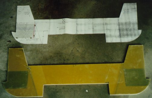
![]()

This is my interpretation of the UND orientation for the aft landing gear bulkhead. The UND layups are the structural tie-ins between the hardpoints, fuselage sides, and bottom installed in later chapters.
Step 5 – Firewall
If I were to build the firewall again, I’d oversize the aluminum laminates for the engine mount from 1 inch square to 2 inches square. I found out later in Chapter 23 that it’s hard to make an engine mount that will fit to the exact dimensions shown in the plans. Welding creates a lot of heat, thus causing the engine mount also bends and contorts with the heating and cooling cycles. Thus, the footpads on the mount won’t exactly be on center. Mine were very close to falling outside of the laminates.
I used bolts instead of screws for the blind installation into the firewall. I carefully chiseled out hex holes into the firewall to fit the bolts, drilled and safety-wired the heads, then glassed over them with the 1-BID. I did this so they won't turn on me when installing the rudder pulleys in a later chapter. If you don't know this story, the Long EZ drivers have complained for years about the bolts turning. The only remedy is to slot the bolts at the thread ends, then install the pulley and nuts. I'm not going to chance it.