Building a Cozy MK IV
Plans number 1573.
Chapter 6
Fuselage Assembly
Click on the pictures for a larger
image.
Click on pictures for larger views.
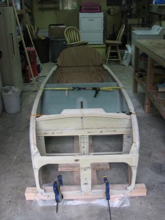
Next I installed the temporary firewall to the fixture making sure that it is plumb and the slots for the upper longerons are at the proper waterline. I then trial fitted the bulkheads in place one last time, checking that their locations are correct and that they are plumb. I also rechecked the overall length again (which makes about the 15th time) being that it is so critical. I drilled small holes through the fuselage sides and installed small nails through the wall into the bulkheads and seat back to hold everything in place. I disassembled everything. Using slow cure epoxy to give me some time to work, I mixed up some thick flox. I then began assembly from the rear with the seat back first, floxing each bulkhead back in its place checking again that they are perfectly in their correct position and that they are perfectly plumb. I reinstalled the nails and I made sure that there were no gaps between the fuselage sides and the bulkheads or seat back. Everything fit amazingly well. I next used a ratchet strap (ratchet strap was overkill, I wouldn't suggest doing that) and budgie cords to hold everything tight together until the flox has time to cure. Below is a picture of the fuselage completed to this point. Well crap, the front bulkhead was installed backwards with the doubler on the wrong side. I carefully cut the bulkhead off, sanded everything down again and reinstalled it correctly. I re measured everything and rechecked everything for level and plumb. I next made flox corners on all of the bulkheads and the seat back to prepare them for the glass taping. Below is what it looks like to this point.
I
ordered all of the materials needed for the next three chapters and enough
epoxy to get me through the winter (like a Squirrel getting ready for winter). While waiting for the
materials to get here, I finished fiberglass taping all the bulkheads
and seat back. Next I laid out the heat duct parts on a piece of Clark's
foam that I had left over from a previous chapter. These will get glassed still
in sheet form, and then they will get cut out of the sheet. Picture
below before glassing.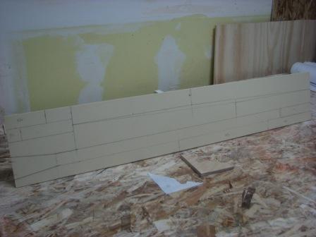
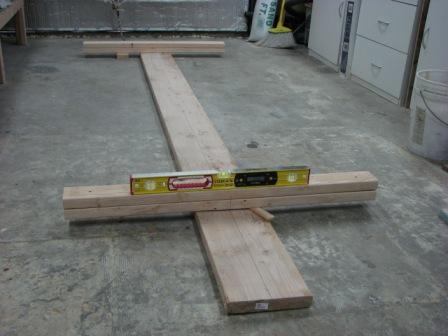
After
fiberglassing and cutting the heating duct parts out of the sheet, I made
a fixture to assemble the parts with. I started out by cutting blocks of
2"x4"'s to the proper lengths to support the top of the heating duct . The 1
1/2" thickness of the 2"x4"'s are already the correct size for the inside
dimension of the duct except for the end with the flare, which is shown in the
picture. I then screwed the block to my workbench, keeping them perfectly
aligned. Next I covered the blocks with clear box tape to keep the heating duct
from getting glued to the blocks.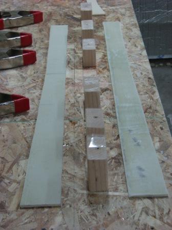
Then I
test fitted everything on the fixture and checked the heating ducts finish size
to make sure it will be correct. I dissembled everything and floxed the
mating edges and reassembled the heating duct and clamped it.
The
next day I unclamped the heating duct and removed it from the fixture.
This fixture worked great and took no time to throw together. I then removed the
foam from the top of the heating duct for the seat belt hard point. I
installed the aluminum tube used for the seat belt hard point. I then glassed
over the hard point with 7 layer of UND fiberglass. I made a bracket to hold the
fuel tank selector valve which will be located in the seat brace per plans. Not
the John Denver location. I glassed the outside of the heating duct with
BID fiberglass. After it cured I cut the excess fiberglass off and fitted it on
the fuselage. I built the front seat back brace and floxed the fuel selector
valve bracket in place. Sorry no pics of that. I glassed the seat back
brace in place on top of the heat duct.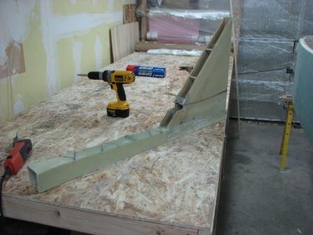
I Bondoed the saw horses to the
garage floor and leveled the fuselage. I then Bondoed the fuselage to the saw
horses to make sure nothing moves. I floxed the seat brace and heat
duct in place and taped it per plans, making sure that everything stays square,
plump and straight. Below is a picture of the seat brace and heat duct
fiberglassed in place. The fuselage is still upside down on the saw
horses.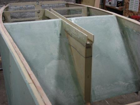
I took the foam for the bottom of the fuselage and positioned it
in place. I added weights to the top of it and climbed under the fuselage and
marked the positions of the stringers, seat back, instrument panel and the heat
duct.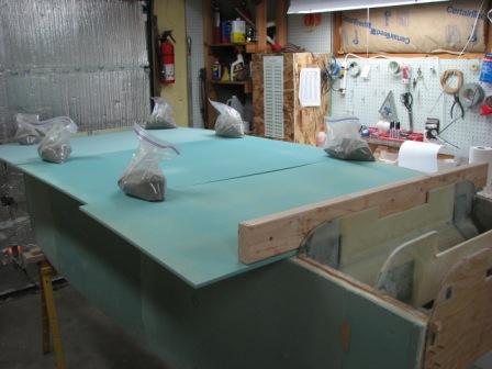
I took it over to the work bench and marked the cutting line
3/4" out from the stringer lines. I cut the foam and used 5 minute epoxy to
glue to ends of the sheets together. I placed it back on the fuselage and
checked the lines again. While it was still on the fuselage, I ran 2 2"x 4"
running length of the fuselage making sure they far enough out to clear the
landing brake (it gets cut out next) and I took some 1" x 3"'s and ran them
perpendicular to the fuselage and Bondoed them in place. This was done to
maintain the curvature of the fuselage bottom when I move it to my work
bench.

Next it
all went back to my work bench turned over. I marked and cut
the landing brake out of the foam with a jig saw set to a 45 degree
angle.
I then began laying out the 3/4" Last-a-Foam and found out that there
is not enough in the "kit" (you buy a chapters worth of materials and the
supplier calls it a kit). The Last-a-Foam is to give depth to the bottom of the
fuselage and it will also give a little more material to work with when I shape
the outside of the fuselage. This chapter comes to a screeching halt until more
Last-a-Foam gets here. While waiting on this to get here it looks like I
can start on Chapter 8.
The Last-a-Foam has arrived so back on chapter 6. I finished
cutting and shaping the foam parts for the bottom of the fuselage and laid them
in place. I marked the location of the Last-a-Foam on the bottom of
the fuselage so that when the epoxy is mixed, I wont need to measure
everything out. Below is a picture of the fuselage ready to have the Last-a-Foam
microed to the fuselage bottom.
Next I
microed (mixture of micro balloons and epoxy) the Last-a-Foam parts to the blue
foam and inserted small nails to hold it in place until the epoxy set up. I then
cut the fiberglass cloth to size in preparation for doing the layups on the
fuselage floor. These layups will take a while to do so I will need to wait
until the weekend to do that.
Below is a picture of the floor fiberglassed
and floxed in place. Next I climbed under the fuselage and fiberglass taped all
the corners whit two layers of fiberglass. What a pain. This ended a 12 hour day
of fiberglassing only. The 12 hours didn't include all the prep work like
cutting the fiberglass cloth, laying it out on the fuselage floor and cutting
all the tapes.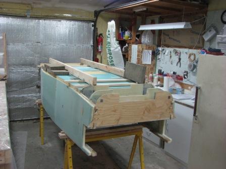
The
next day I removed the wood framing and checked out my work and didn't see
anything needing repaired. Below is a picture of the fuselage with chapter 6
completed. The white area is the landing brake cut out of the
fuselage.

Below
is a picture of the inside of the floor trying to show the contours that the
Last-a-Foam formed. It gives the floor some depth and keeps it from looking so
flat.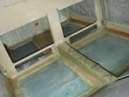
This
completes chapter 6. Ready to start chapter 7.
If you have any questions, comments or concerns,
feel free to email me at Jfisher59@gci.net
.