Chapter 23: Cylinder Baffles
Step 7: Cylinder Baffles
(In work)
(Updated 4/9/2012)
(Not per plans)
My cylinder baffles form two sides of my contained plenum under the engine. As such, the baffles extend down to the cheeks on the lower cowl. Very different from the plans.
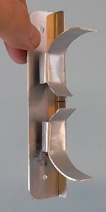
These two pictures are the baffles for Cylinder 1 and 3. The baffles are made as two, overlapping pieces to account for thermal expansion and vibration between the cylinders. I bent part of the Cylinder 1 baffle inward to get it away from the top cowl.


Ah hah, you say! What about the exhaust pipes? Bingo! That was the biggest technical challenge with this configuration. I solved it by allowing the exhaust pipes to pass through mouse holes in the baffles. I sealed around the exhaust pipes with fiberfrax gaskets and mouse hole covers.

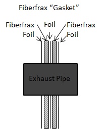

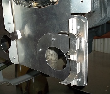
The mouse holes are obviously the cutouts made in the cylinder baffles as shown in the pictures above. The first picture below shows the mouse hole covers. Note how the opening are different for each exhaust pipe. The openings provide a > 1/8th inch gap between the covers and the pipes. That gap will be sealed with gaskets made of alternating layers of foil, RTV, and fiberfrax. Fiberfrax is a brand name of ceramic cloth that is fire-proof to well over 2,500 degrees F sustained. The gaskets will fit snugly around the pipe. You betcha, I will flame torch a few gaskets to ensure they are indeed fireproof. The second picture shows a bracket that secures the exhaust pipes to the cylinder baffle/aft baffle. They are not as elegant and certainly not as strong as what James Redmon uses. But I will go with these for now and change out to his version later. The third picture shows what the two mouse hole covers look like without the exhaust pipes. You can clearly see how the exhaust pipe bracket will work. Note the smaller bracket attached to the Cylinder 3 baffle. That bracket -- when clamped to the exhaust pipe -- provides stability for the baffle and keeps it from vibrating in and out. The fourth and fifth pictures show the completed baffles with the exhaust pipes and brackets in place. The fiberfrax gaskets are not installed in any of these pictures (because I haven't made and tested them yet). I will cut off the extra lengths on the hose clamps later.