Chapter 20: Winglets and Rudders
Step 7: Installing the Rudders
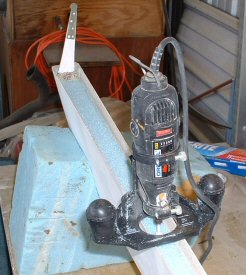
Cutting Out the Rudders
(Note: I installed the hidden bellhorns and contoured the winglets BEFORE cutting out the rudders.)
After installing the hidden bellhorns and contouring the winglets, I proceeded with cutting out the rudders. I applied masking tape along the approximate locations of where the rudder cut lines would be. I very carefully marked out the rudder dimensions. (See Addendum below.) This is definitely one of those "measure twice, cut once" scenarios! I cut the rudders out by holding a straight-edge up to the lines and cutting through the lines using a sharp razor knife. I didn't want to use a dremel tool and cutting wheel because you can't hold the dremel tool perpendicular to the cut lines, plus it opens too wide of a gap. Once the fiberglass skins were cut through, I used a hacksaw blade to cut through the foam. Of course, I remembered that the bellhorns were in there too. It would be disastrous to saw through those things! Because I am MUCH craftier than Mr. Slade, my pocket approach to installing the hidden bellhorns worked perfectly and I had no trouble pulling the rudder from the winglet.

(Addendum: Okay, true confession time. My rudders are 3 inches taller and a half inch wider (fore to aft) than stated in the plans. Since I wasn't going to install the lower winglets originally, I added 3 inches to the top of the rudder to recover some of the lost surface area normally provided by the cut-outs into the lower winglets. Nat did this, too! He originally didn't use the lower winglets either, so he added 3 inches for the very same reason! As for the wider rudder, I followed Ken Miller's lead and made that change to get rid of needing the rudder cable compensation springs. By moving the rudder hinge line a half-inch forward, you get more rudder travel -- 30 degrees as opposed to the 26 degrees maximum stated in the plans. I can now engage the brake cylinders at 22-26 degrees rudder travel and bottom out the cylinders before reaching 30 degrees travel. Therefore, I no longer need the rudder cable compensation springs.)
Glassing the Spar Areas
I hollowed out the foam for the spar areas according to the plans. I used my dremel tool with the router attachment. I made a paper pattern for the winglet and rudder spar areas. After slurrying the exposed blue foam, I used dry micro and applied small fillets in all corners. Micro fillets are important here. The corners formed between the foam and the skins are at very sharp angles. The fillets are necessary to help the 3-BID to fold into the corners. Else, the cloth will pull away and form air bubbles. However, the fillets must be rather small, or else will compete for space with the hinges that are installed later. I guess if you had the right bit you could route out the foam leaving a foam fillet. I wet out the 3-BID layups onto saran wrap and used the patterns to cut the 3-BID layups to shape. I then transferred the layups into the spar webs and stippled them into place.

Installing the Hinges
I notched out the rudders and installed the hinges as per plans. I did switch to a dash 4 series hinge instead of the dash 6 as specified in the plans. Why? Because the dash 6 hinges end up being too wide to fit in the spar areas. The plans said to hollow out the foam in the spars to be 1 inch deep. The dash 6 hinge halves are 1 inch wide. But by the time you pile in the 3-BID and notch out the winglets by 0.2 inches, the spar depth ends up being alot less than the 1 inch required to fit the hinge halves. The dash 4 series is only 0.75 inches wide. So I used that instead of cutting and custom-fitting the dash 6 series.
Getting the hinges installed onto the winglets were a piece of cake. But ingenuity is required to correctly drill the holes into the hinges for the rudder. I tried my "hacksaw" trick I used for installing the aileron hinges, but the hinges are recessed too deep to get the hacksaw blade in there. I first laid out and drilled the holes into the rudder. I then stuffed some small, blue foam blocks into the rudder spar area at each hinge location as shown in the picture below. Placing the rudder onto the winglet, it was a simple matter then to slip the hinge halves into place between the rudder skin and the foam blocks. The purpose of the foam blocks was to serve as a backing surface to have something to hold the hinge halves against the rudder skin as they were being drilled.

Installing the Return Springs
BIG WARNING!! DON'T MUCK UP THE ANTENNAS! The instructions say to drill the 1-inch holes and install the tubes along the inside skin. Remember that the copper strips are under the inside skin! Give yourself a little extra room when drilling that hole. The plans also say to shape some music wire and pot it in place with flox. This is another one of those "herding cats" episodes. I did something easier. I just bought some small picture frame hooks at Lowes and screwed them in to these cute, little wood plugs I made from quarter inch plywood. I bent the ends of the hooks over the face of the plugs so they can't ever come out. I glued the plug onto the end of the tube and installed the whole thing into the 1-inch hole. I used these same hooks on the rudders, too, (without the wood plugs). I just bent then at 90 degrees again, drilled a small hole in the rudder spar area, and slipped them under the skins with some flox.

[Previous] [Home] [Next]