Chapter 17: Landing Brake Actuator
Step 3: Landing Brake Actuator
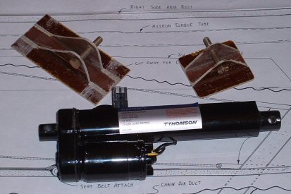
I elected to use the electric linear actuator instead of the manual hardware. The actuator I'm using is the Thompson "Electrak 1", a 12-volt linear actuator with a 4-inch stroke, rated for a 75-pound load. The numbers on the label are "S12-17A8-04" and "9307-448-002". The unit deploys and retracts in about 4 seconds. It has its own internal microswitches that shut off power at end of travel.
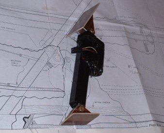
Builders normally mount the upper end of the actuator to the side of the center keel brace. After studying the M-drawings, I noticed that if the actuator was mounted to the seatback, then the angle of the actuator is virtually the same when deployed or retracted. The body of the actuator hardly moves fore or aft! Thus, all you need is an oval hole instead of a large, wide slot. So I decided to do that. I made the custom brackets you see here from 8 plies of BID. The upper bracket is bolted onto the back of the seatback, immediately adjacent to the side of the center keel brace. The upper bracket is slotted so I can slide it up or down on the seatback for adjustment. The smaller bracket is made to replicate the plans bracket that gets mounted onto the landing brake itself.
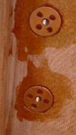
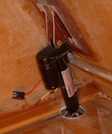
Once I located the proper position, I glassed some EZ-points into the aft side of the seatback. I usually drill 4 holes into them to help the flox hold them from spinning. You can see a close-up of the EZ points in the picture on the left. I then applied an 8-BID pad over the EZ-points. I wanted the thicker pad there to help spread the load from the actuator when the brake is deployed. Once cured, I ground away the glass to open the hole to the EZ points. The finished product is shown on the right. The hole through the floor doesn't need to be this big. I got confused when I was lying on my back under the plane and I ground away too much material on the wrong side. So I will glass over the floor and reduce the opening a bit. BTW: That slot you see aft of the hole is the slot I cut out back in 1999 per the plans. You do not need this slot if you're going to use the electric actuator.
The next steps are to make a cover to completely enclose the actuator. I'm also planning on installing a small position sensor to the landing brake so I can monitor how much the landing brake is deployed. It's so rewarding to watch this thing go up and down!