Chapter 16: Assembly and Trial Fit
Step 3: Assembly and Trial Fit of Parts
Once I got my head around which tube goes where, it was time to assemble and trial fit the forward and aft control assemblies.
The first step is to drill the holes. The goal is to drill holes in the ends of the tube, 180 degrees apart, so the bolts are installed straight and true. I used two old tricks to index the tubes and locate the pilot holes for drilling. As mentioned in the plans, most of the bolts in the control tubes are installed vertically. So it helps to index the tubing so that the bolts are lined up on each end. The tubes and what goes inside them -- either the steel inserts or the universal joints -- are best drilled with one of those expensive fixtures that holds the drill bit perfectly perpendicular to the tubes. I didn't have such a jig, so I used a different approach. It sounds very anal, but if you don't have one of those expensive fixtures, the drill bits will walk around and the two holes will not line up. This process is one way to minimize the misalignment that naturally occurs.
Here's my process:
1. Set the tube onto a C-channel extrusion and make index marks on each end. Wrap a strip of paper around the tube, then fold the paper in half to find the opposite side. Mark the locations for the holes, then center-punch them prior to drilling. The aluminum tubes have thin walls, so I didn't get too aggressive with the center-punching, lest I should squash the tubing. Later, when installing and riveting the CS1A rod-end fitting into the canard and aileron push-tubes, the plans call for two rivets to be installed perpendicular to each other at 90-degree angles. I used this same paper trick to locate those holes. I simply fold the paper again into quarters to locate the 90-degree points for the rivet holes.


2. Position the steel insert (or universal joint) into the tube and drill a small pilot hole through the first side of the aluminum tube and its corresponding insert. "Pin" them together by inserting another drill bit of the same size through the pilot hole. I do this so the insert (or universal joint) won't move or rotate around inside the tube as I drill the opposite pilot hole.
3. Rotate the tubing to the other side and drill the second pilot hole. With the first pilot hole still "pinned", drill out the second pilot hole with progressively larger and larger bits until reaching the final diameter. Insert a short AN-3 bolt in the hole to "pin" the tube and its insert. Remove the drill bit used to pin the first hole.
4. Rotate the tube over and progressively drill out the first pilot hole. Once the hole is to the final diameter, remove the bolt and run the drill bit all the way through the tube and its insert to ream the holes and align them as best as possible. I know the plans say to use a #12 bit, but I don't have indexed bits. It doesn't seem to matter in the long run because once I bolted the tubes together, it's a very snug fit anyway. Ain't nothin' gonna move.
5. When drilling the tubes for the forward control assemblies (CS 105’s, 106’s and 107’s), I held the tubes tightly against the nylon bearings and washers to take out all play. The movement is very stiff right now, but this is on purpose! Once I install the control system for good, I will gently sand the ends of the tubes at the bearing blocks to a custom fit that will allow free movement with zero play.
6.
Once all the parts were drilled, I assembled them and did a quick check-fit.
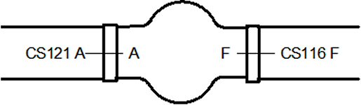
I carefully labeled and indexed all tubes and inserts so I knew which tube went where
with what orientation so the holes would match up later during final bolting.
Otherwise, I would have had quite a jigsaw puzzle on my hands.