Chapter 13: Rudder Pedals
(Updated 9-7-10: I'm going to change the geometry of the brake actuators to provide the more ideal 2.5 to 1 geometry that Matco recommends. Stay tuned for updated photos in a few months.)
Even before buying the plans I knew I was going to do something different with the rudder pedals. I wanted more room for my feet, and it's my opinion that the plans rudder pedals take up valuable real-estate. So I wanted to move the rudder pedals away from the sides and remove the clutter of the torque tubes running across the floor pans.
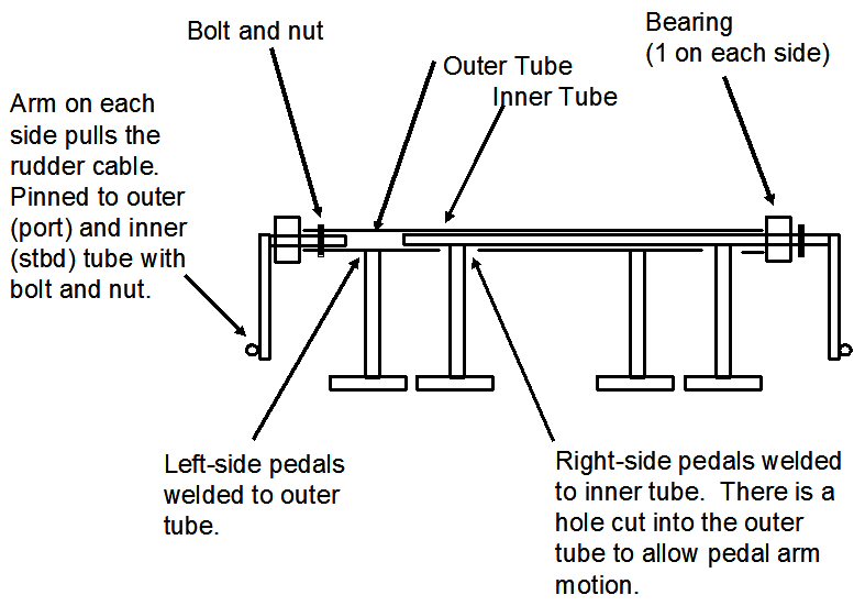
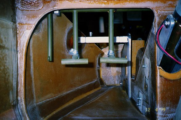
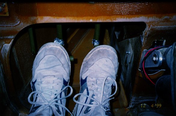
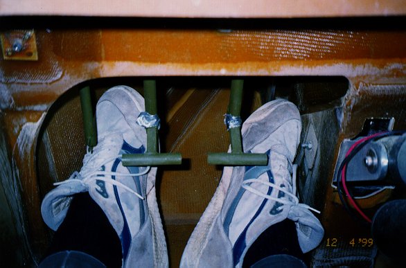
I'm using a set of Velocity rudder pedals hung vertically from the F-22 bulkhead. If you've never seen them, they look like a more traditional pedal set-up. The pedal assembly is actually a concentric, “tube within a tube” arrangement as shown below. The geometry is identical to the plans pedals, just inverted. They function exactly like the plans pedals. In fact, the T-bars are located at the same height (7 inches) above the floor pans. As these pictures attest, I now have the most foot room allowed by law. (Note: In retrospect, I could have used the plans-built pedals and torque arms, inverted them, and achieved the same results.)
Of course, every time you do something different than plans, you have to modify something. In my case, I had to develop a different approach for hanging the rudder pedals and for anchoring my brake cylinders.
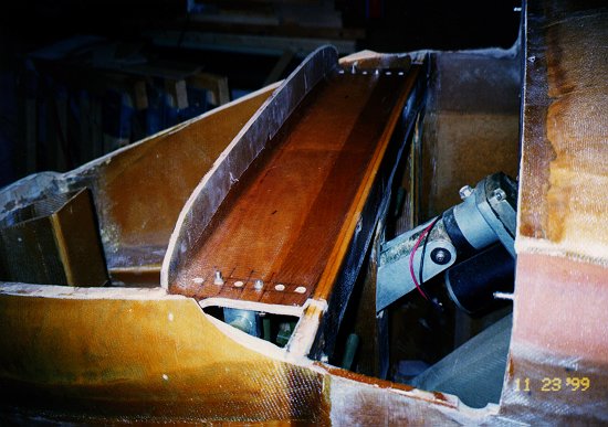
Remember that PVC bracing that's installed forward of the canard from F22 to give structural support to the nose top? Well, instead of making it from PVC foam, I made a shelf from birch plywood, glassed both sides with 2-BID and taped to F22 and the nose sides. This shelf now serves double duty by providing something structural from which to hang the rudder pedals and for providing structural support for the nose top. I drilled a series of holes into the shelf for attaching the torque arm bushings. These holes allow me to adjust the fore/aft position of the pedals to accommodate longer and shorter human legs. The T-bars are also adjustable fore and aft too.
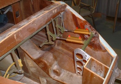
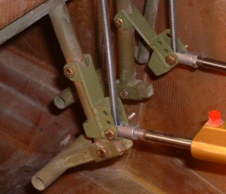
Since these Velocity pedals are an "inverted" approach from the plans, I also had to invert the brake cylinders. Anchoring to the floor pans obviously would not work. As many of you have pointed out, I could have easily anchored the brake cylinders to hardpoints in the sides of the nose. I essentially did that with the port pedal. But there are two reasons why I didn't do that for the starboard pedal. First and foremost, I plan to make the passenger's rudder pedals removable so I can take them out when flying with non-pilots. This would give them more foot room and it would lessen the chance of an accident. There have been occasions when passengers mistook the rudder pedals for footrests! Secondly, I wanted to do away with the reported "mushy" feel in the starboard brake caused by the slight twisting in the torque tube by the pilot's starboard pedal having to operate the brake cylinder located a few feet away.
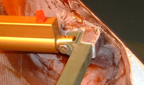
On the Velocity aircraft, the brake cylinders are mounted directly to the pilot's pedals. This solves both issues, so I chose to adopt that idea. I suspended a steel tube between a hardpoint in the port side of the nose and a triangular stanchion bolted onto the port side NG30. So I no longer have "lay-down" cylinders any more. :-)
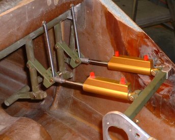
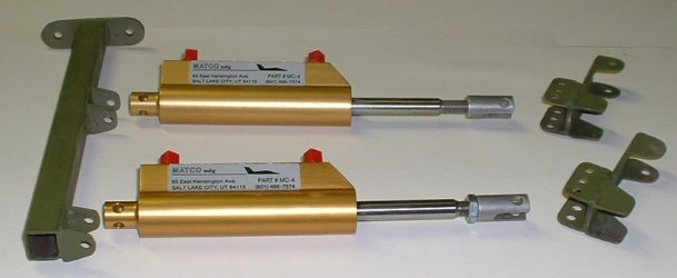
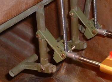
I decided not use the sliders shown in the plans. While they work just fine, you cannot adjust the amount of rudder pedal travel you get before engaging the brakes. Since mine is a first-of-a-kind installation, I wanted to be able to adjust this travel to optimize the design without having to make new sliders each and every time. As you can see in these pictures, this is provided for nicely by the actuator arms. The actuator arms are made from ¾-inch channel and are just shy of 3 inches long. One end pivots on the rudder pedal arm. The cylinder rod pivots at the other end. As the rudder pedal is pushed forward the actuator arm rotates downward until it is fully engaged by the rudder pedal arm. Further forward movement of the rudder pedal depresses the brake cylinder and engages the brakes. Springs help return the system back into their initial positions once you take your feet off the pedals. To adjust the rudder pedal travel, you simply screw the threaded coupler in or out, or change holes in the actuator arms. If you want a really firm braking feel, simply use a higher hole on the actuator arm. Use the lower holes for a softer, less firm setting. There have been numerous one-off pedal systems throughout the years, but I think I’m going to like this one. No parts to wear out, jam, or break. Nothing sliding around. And I can visually inspect the entire system from the front nose hatch.
(Updated 9-7-10: As I mentioned above, I will be changing this arrangement to obtain the more ideal 2.5 to 1 geometry that Matco recommends. The easiest "fix" is to move the actuator arm pivot points higher up on the rudder pedal arms. This will allow the brake cylinder pistons to intersect where the pivot point is shown now. Stay tuned!!)
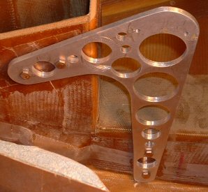
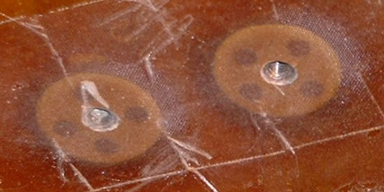
Every plane must have a conversation piece, and this is one of mine. This aluminum stanchion, which holds the other end of the steel bar, is bolted to EZ-Points floxed onto the port NG30. I chose a big, honkin' piece of aluminum because I could thread the holes. Later, I discovered that EZ-Points make life easier. So I decided to put the stantion on a diet by testing every hole saw I had in my inventory. EZ-Points are like clickbonds, except these are females for AN-3 bolts. I drilled four holes in them before floxing, then applied 1-BID over them to ensure they don't turn.