Chapter 13: Nose Gear
I got the Featherlite pre-fabricated nose strut, nose cone, nosewheel bowl. These are very nice pieces. I also bought the strut insert (cover), but didn't use it. It's purpose is to seal off the area between the NG30 bulkheads. But it's useless because you end up cutting a majority of the cover away once you cut all the holes for the nose lift mechanism I am using Jack Wilhemson's NG6 strut casting. Very nice piece of hardware. I ordered Steve Wright's electric Noze-Lift. It's a fine-looking unit, well-made, and costs only a few hundred dollars more than all the mechanical Brock hardware. Most builders of completed planes say adding the noze-lift was the first mod they made once the plane was finished. Most people are concerned with using the socket wrench to crank the gear down if the unit fails. I personally believe you'll only hand-crank because of an electrical problem with the plane, not the unit. I'm planning on implementing a backup electrical circuit that connects the unit directly to the battery so that if my alternator fails in flight, I can still electrically lower the gear.
Thanx to James Redmon, here are some movies of the nose gear deploy/retract sequence and some close-up movies of how the nose gear doors open and close. James has built and is flying a nice Berkut. His nose gear system is slightly different from mine, but the movies will give you the general idea.
Movie: Nose Gear being Retracted (1.2 Mbyte file)
Movie: Nose Gear being Deployed (1.3 Mbyte file)
Movie: Gear Doors Closing (541 Kbyte file)
Movie Gear Doors Opening (478 Kbyte file)
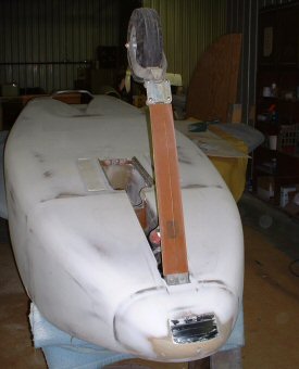
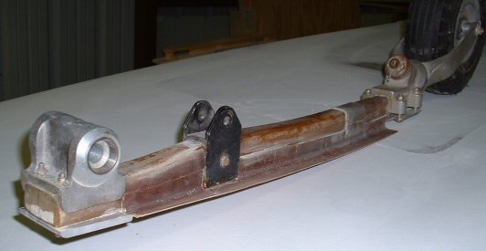
Nose Strut
1. I cut my strut one inch longer than plans. These planes lift off faster when the plane is at positive angle of attack to the runway. I can always trim it down later if it's too much. (NOTE! This is NOT to say that my canard is installed with positive angle of attack. My canard is installed with zero angle of incidence to the fuselage, exactly like it's supposed to be!)
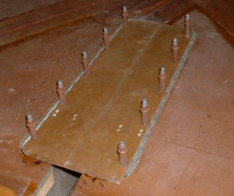
2. I followed the steps for the nose gear strut with the exception that I used a thicker backing plate. I also put a skid pad under the nose instead of just a hockey puck. A lot of canard drivers do this to function as a skid pad to protect the nose for the inevitable gear up landing.
3. Step 10 of the plans has us glass the nose strut cover directly to the nose strut, then apply 1-BID tapes onto the backside of the cover that overlap onto the sides of the nose strut. This certainly works to secure the cover to the strut….but it works TOO well! The strut has a tendency to flex on hard landings, which over time causes the cover to detach from the strut. Look for this at your next canard fly-in! The backside BID tapes are usually torn or delaminated on the lower half of the nose strut. What’s needed is a method that allows the lower half of the strut cover to float when the nose strut flexes. The diagram below shows what I did. The backside BID tapes are bonded to the strut only from the NG6 casting to 4 inches below the MKNG-3 nose-lift bracket. They are NOT bonded on the lower half of the strut and are free to float when the strut flexes. What I did was cover the sides of the lower half of the strut with black electrical tape (for mold release). I also applied electrical tape over the strut where the bracket would go. I then applied the 3-BID tapes to the cover and against the release tape, and over the strut as shown. Once cured, I removed the release tape. Three plies of BID sounds excessive, but the thickness is primarily to hold the shape of the lower half of the strut cover. So what I ended up with is a strut cover that's held firmly in place, yet can still float on those less-then-perfect landings. In case you're wondering, why did I wait 7 years to fabricate this cover? Well, when I constructed the nose section (in 1999), I failed to properly align the floor pans with the fuselage bottom. They somehow ended up not being flush with the bottom. So I waited until Chapter 25 to fill the bottom of the nose and contour it flush with the fuselage bottom. With everything contoured I could then make a strut cover that conformed perfectly.

Nose Gear Doors
(Not in the plans)
Here are a few pictures of my nose gear doors. I know the plans say you don't need them, but hey, I just wanted ‘em. So I put them in. To make the doors, I cut out the bottom skin, epoxied a thin sheet of clark foam for rigidity, then glassed 3-BID over that. I made two birch strips and installed some aluminum inserts for attaching the hinges. The birch strips are imbedded between the inner skin and the outer skin. I flush-mounted the doors in place, then match-drilled the hinges and inserts. A spring gets installed between the two doors. It holds the doors open when the gear is deployed. The doors are also angled with the forward opening a little bit wider than the aft opening so that the onrushing air will hold the doors open too. When the gear strut comes up, the strut grabs the spring and pulls the doors shut. All this was done in 1999. Years later in Chapter 25, I added some mechanical stops inside the wheel well so the doors would stay flush with the exterior surface when closed.
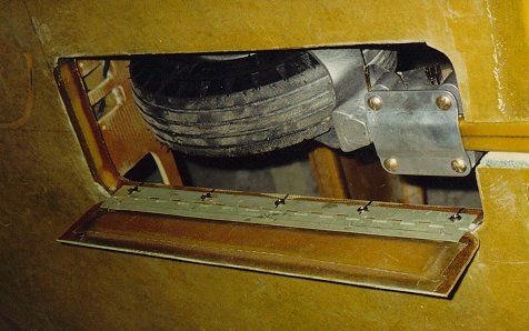
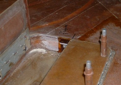

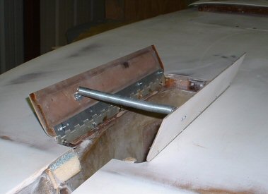
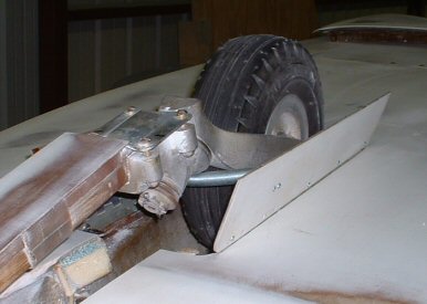
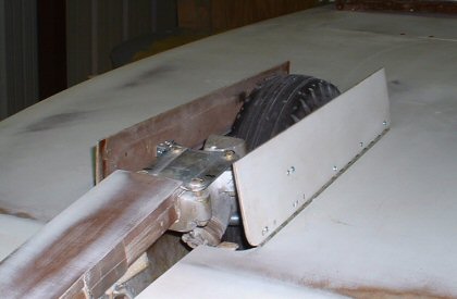
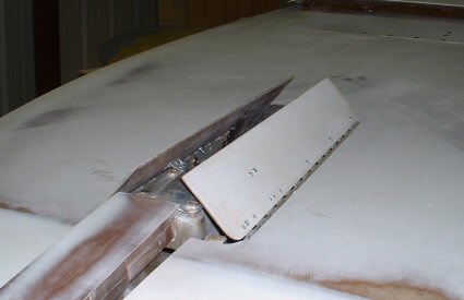
Here is the door closing sequence. As mentioned above, the spring is all that holds the doors open. A spring's tendency is always to be straight. Bend it in half and it will want to pop back straight. So in this application, its tendency is always to push the doors open. The doors will only close when the strut pulls the spring into the wheel well. If the strut is not there, the doors will pop open. It's a very simple system that is virtually risk-free. As the nose gear is retracted, the spring is captured by the "nook" of the casting that's just above where the fork pivots. Further retraction causes the spring to be pulled down into the well, which causes the doors to close against the tire. This sequencing is critical! The doors must not close early, else the door edges will snag the tire axle bolt or the backing plate of the nose wheel casting. This will ruin your day. You might be able to note the little black marks on the inside of the doors where it rubs momentarily on the tire as they close. This is normal. The last two pictures show the final closure of the doors.
James Redmon and a few others have added a hoop made of music wire. James added it to his doors to limit how far the doors go open, to keep the doors from swinging side to side, and to ensure the doors sequence in unison. I may add the hoop later on. Note how wide the doors are when opened. This may be too wide, so I may shorten the spring some day.
Check out the movie sequences provided above for gear deploy/retract sequences.