Chapter 23: Engine Cooling Baffles
Step 7: Engine Cooling Baffles
(In work)
(Updated 9/19/2011)
The templates in the plans were of little use to me. My Lycoming IO-360 wide deck is vastly different in shape and size than the O-360 narrow deck engine specified in the plans. I purchased the firewall forward baffling kit from Van's Aircraft to help speed things along, What a great decision! I was able to use seven of the nine baffles sent with the kit -- the four outer baffles that bolt over the valve covers on the cylinder heads and the three baffles that form what to us in the forward baffling that spans across the top of the engine. I wasn't able to use the two inlet ramp baffles that are specific to the downdraft cooling configuration. The kit also came with other metal reinforcing pieces, the soft rubber baffling seals, and a gazillion bolts, nuts, and rivets. The kit was well worth the money.
The kit doesn't come with a complete set of barrel baffles, inter-cylinder baffles, or cylinder head baffles. I made them from scratch using cardboard patterns, then transferring the pattern to metal, then bending up the metal. I will also need to make the aft baffling than spans across the underside of the engine.
Cylinder Outer Baffles
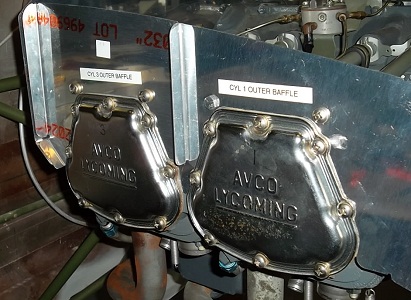
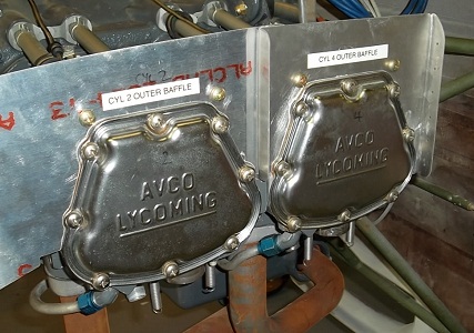
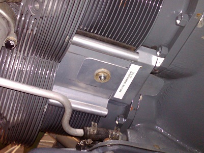
These are the four outer baffles provided in the kit. I had to do some minor trimming in one or two places around the valve covers and the valve cover gaskets. I haven't trimmed the baffles yet. They are made to fit under an RV cowl and are way oversized for what we need. I will cut off the extra metal later.
Forward Baffles
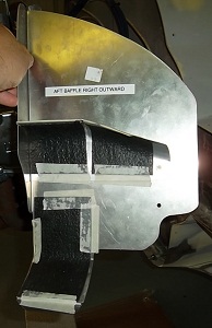
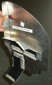
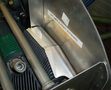
The Vans kit provides three baffles that form the forward baffling that goes across the top of the engine. These are pictures of the outer right panel that fits around cylinder #4. It comes with the metal tab that wraps under the cylinder head fins. It is meant for round cylinder heads. It took all of 5 minutes to bend and reshape the tab to fit around my square cylinder head. The baffling kit does not come with any baffles to cover the cooling fins on top of the cylinder. I made the one shown here in the pictures. I used paper templates, then transferred the pattern to metal, then cut and shaped the metal. I riveted it to Vans panel. Notice that I am using some black lining material. It is my intent to line all baffles with 0.025 high temperature silicon material. The purpose is to seal the gaps between the baffles and the edges of the fins and to keep the baffles from vibrating and chafing. I'm using some tool shelf liners for trials while I'm building the baffles. I'll RTV the silicon material in place once all the baffles are fabricated.
Inner Cylinder Barrel Baffles
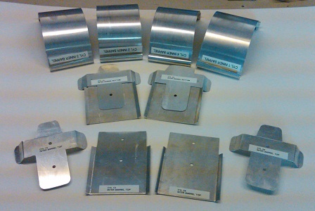
The first picture shows the parts needed to baffle between the cylinder barrels. The four inner cylinder baffles are shown in the top row. The bottom inter-cylinder baffles are in the middle row. The top inter-cylinder baffling plates and straps are on the bottom row.
The inner cylinder barrel baffles wrap around the barrel fins. (Sorry, no picture.) They span from approximately 1 o'clock to 5 o'clock and from 11 o'clock to 7 o'clock. These are made from 0.025 aluminum sheet. An A&P friend is allowing me to use his metal bending brake and rollers. The rollers make quick work of curling the baffles to fit around the barrel diameter. I used a vice to curl the ends around a 9/16th inch rod.
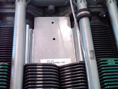
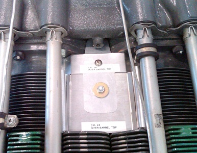
The inter-cylinder baffles block off the area between the cylinder barrels and the crankcase. I had to make the top baffles in two pieces. It was the only way I could get the baffles to fit into place on the engine. The top baffle plate is shown in the second picture. It spans across the inner cylinder barrel baffles and to the barrel bases. The tops plates are made from 0.065 aluminum. These need to be stiff because they help hold the inner cylinder baffles against the barrel fins. The strap is shown in the third picture. It is bent up in such a way as to block off the space between the last fin and the barrel base. The little finger on the strap fills the gap between the cylinder bases and the crankcase. The straps are made from 0.025 aluminum. They are held to the plate with a screw and nutplate. The bottom inter-cylinder baffling plate is shown in the fourth picture. They are exactly like the top plates except that the straps are riveted to their plates. (I guess I could have made the bottom plates as one-piece. But it was easier to bend up the 0.025 strap than it would have been to bend 0.060. Plus, it was easier to copy and fabricate from the top plates.) For now, each top and bottom plates are being held together by a threaded rod running between the cylinder barrels. I will replace the rod later with a long, AN-3 bolt once I determine the length needed. The plans mention using safety wire. But I'm going to use long, AN-3 bolts.
Inter-Cylinder Head Baffles
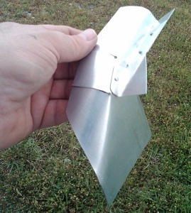
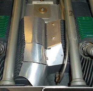
The inter-cylinder head baffles are one-half of the baffling needed to force cooling air through the cylinder heads. (The "other half" is the outer baffles attached to the front and aft baffles.)
The first picture shows one of two inter-cylinder head baffles that get installed onto the top of the cylinder heads. The second picture shows how it is inserted between the cylinder heads. These are made from 0.025 aluminum. It took me a while to figure out how to bend the metal. I scrapped a few of them before I got it right. The top baffles will be held into place with RTV and with safety wire to the bottom baffles.
Trimming the Baffles
I decided to trim the forward baffles and the outer cylinder baffles before starting the aft baffle. As mentioned before, the Vans baffles are too large and too tall. My top cowl would not fit over them. So I removed the Vans baffles and started with templates instead. I made some templates from scrap metal and scrap cardboard. I installed these templates on the engine, then installed the top cowl. Using small squares of cardboard, I reached under the cowl and butted the cardboard squares against the inside of the cowl. This gave me the shape of the inside surface of the cowl. One by one, I transferred the templates to each baffle panel. I drew the outline of the template onto the panel, then subtracted the amount of gap indentified in the plans. I think I'm using 3/4-inch gap on the outer cylinder baffles and 1/2-inch everywhere else.
These picture show I trimmed that right outer baffle. The first picture shows a cardboard template attached forward of the #4 cylinder. The little cardboard squares are butted to the inside of the cowl, then taped to the template. These give me the shape of the top part of the cowl and the shape of the cylinder blister. The second picture shows the template traced onto the Vans baffle. It's important that the template use the same bolt holes as the baffle panel so you can orient the template properly. I traced the outline of the template onto the baffle panel. I removed the template and traced a new line 1/2-inch below the template line. I cut off the excess material with the bandsaw.
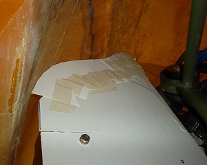
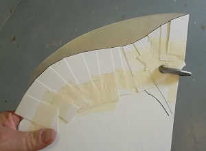
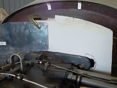
I used this same technique on the other baffles. This next picture shows the trim template for the right forward inner baffle. The left forward baffle has already been trimmed. Don't be alarmed at this picture. The Vans baffles are not high enough to reach the very top of the cowl near the centerline of the engine. The final picture shows the trim template for the outer cylinder baffles.

Aft Baffles
(In work)
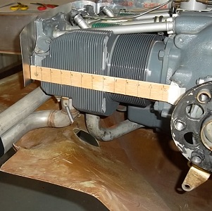
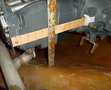
I'm experimenting with making the aft baffle in two pieces instead of the three pieces mentioned in the plans. I have no patterns, so I must template the whole thing. Picture 1 shows a stick installed horizontally between two known reference points on the engine. Picture 2 shows me measuring the distance between the reference stick and the bottom cowl in half-inch increments. Picture 3 shows the measurements transferred onto a template. Picture 4 shows the template installed onto the engine. Again, I used little cardboard squares taped in place to give me the exact contour of the lower cowl. I also taped little squares against the crankcase housings and around the alternator bracket. I will worry about the hole for the alternator later. I transferred the template outline to the baffle plate and drew a new line 1/2-inch above it. Picture 5 shows one half of the aft baffle in place on the engine. Woohoo!!


Next Steps
Make attachment bracket for the left side aft baffle, make cylinder #1 head and barrel baffles, then attach them to the left side aft baffle.