| FireFlys' Cozy Mark IV, #1500 |
|
Dedicated to those that lost their lives on 9/11 |
|
|
 |
 |
|
 |
 |
Chapter 5 |
Building the fuselage Sides |
| This is the chapter where you build the
sides to the fuselage.
Chapter 5 Research Summary (PDF Document) - Please contact me if you have tips/FAQ's that should be added |
TIPS / WHAT I DID...
|
Misc Thoughts...
|
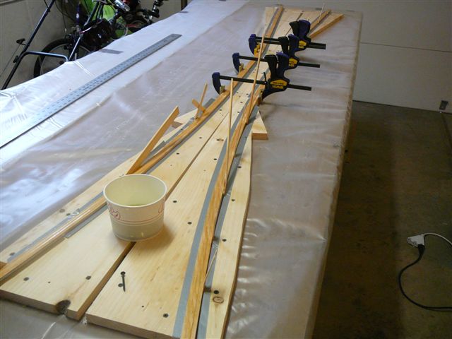 |
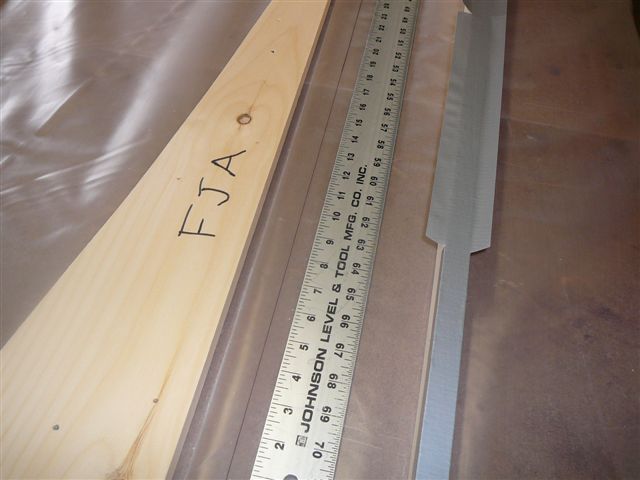
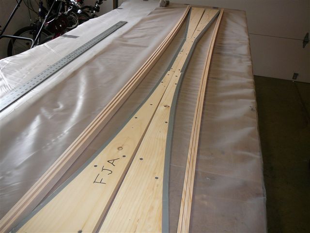
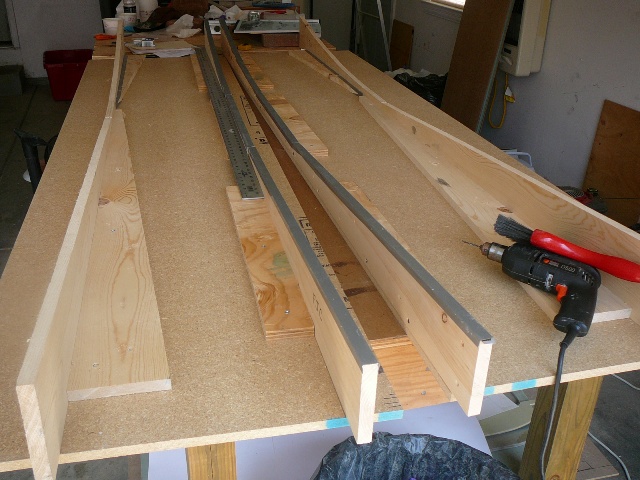
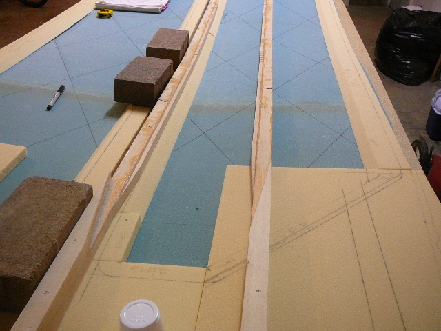
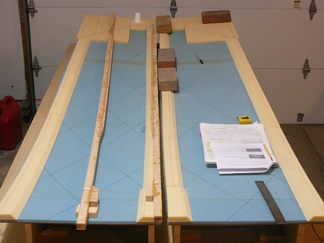
Cutting Jigs / Laminating Top LongeronsScrewed the two 1" x 8" boards together then followed plans to measure and cut the jigs. Used the scrap pieces after jig-sawing part FJA, to help hold the longerons in the jig. Marked a centerline on the table, then covered surface with plastic and wrapped molds (and jig clamps) with duct tape. Screwed forms, through plastic, onto table. Epoxied mating surfaces of spruce and stacked. Once both longerons were epoxied, I positioned them in the jigs and used the clamps and wood blocks to hold in place. Used small wedges to insure that the longerons were placed snuggly against the jigs. I started to follow the suggestion of another builder, and removed the longerons (after sanding excess epoxy from the tops) from the jigs in order to put the doublers on using clamps. The parts came free easily, and while they retained their shape, they did lose some of their "bow" when the clamps were released. I figured that it was better if I left the parts in the jigs until the doublers had been placed and set.Added note - Miscut the rear UL doubler to wrong length (15.25" vs. plans 15.5"). It looks like it will still extend through firewall, but added a little more to be sure. I recommend measuring twice, and cutting once! You may want to consider cutting piece to 15.75" or 16" to give yourself a little cushion. |
|
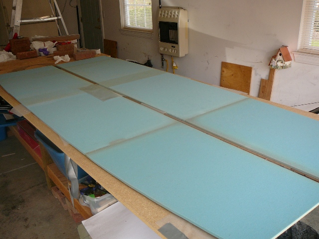
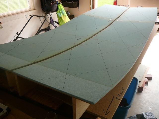
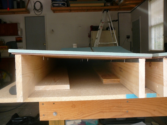
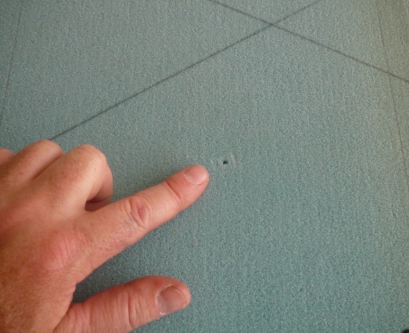
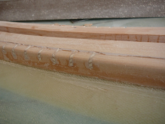
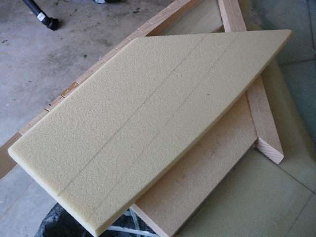
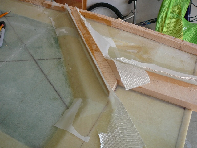
Building the Forms (Fuselage Sides) and Preparing for ContouringFollowing the lead from others, I cut the masonite and foam before setting up the jigs. I measured and cut the masonite first, then used the masonite as a pattern for the foam. Make sure that you line up the "full" sheets of foam from the rear and work forward. This will help you avoid getting a seam at the control stick relief. Also, per Rick Maddy's suggestion, I added an extra 3/8" to the bottom. I marked the 30 degree and 10" lines on the foam for references. Instead of bondo, I attached the jigs to boards that were screwed along a straight line. I built the jigs on two 2' x 8' sheets of pressboard. This will allow me to separate the sides if needed, limit the screw holes into my table, and when finished, the two pieces will convert to doors for a garage cabinet. Due to the curvature of the piece, I found it real difficult to maintain the 7/8" space evenly along the top. I did my best and got it as close as I could. I attached the foam to the jigs using a finish nailer set at a low pressure. I practiced on some scraps to make sure everything worked the way it was supposed to, and after a successful trial, moved to the main piece. The practice peeled of like velcro and left small holes(see picture) that should be easy to fill -- Hopefully, the main piece will come off just as easy. Rough cut out all the 3/4" foam spacers. Since the plans do not provide a lay out on the foam parts lay-out page, I decided to try to create one. Everything was going great (at least in my mind...) until I realized I forgot to check measurements when I moved the rail on the table saw. This caused a few miscut pieces along the bottom of one side (measure twice, cut once...dumbass!!!). I decided to use the miscut pieces when I contour the fuselage bottom, and recut new spacers from the remaining piece of 3/4" foam. Long story short, mine is probably not the template to follow. After everything was rough cut, I finished forming the pieces using the Perma-Grit blocks and sandpaper. FYI - If you plan on cutting the angles using a saw, Jeff Wilson has calculated the angles for AA, BB, CC, and EE as 35, 33, 34, and 17.5 degrees, respectively. Following the lead of others, I used Rick Maddy's guide for the electric channel (6" from back, 3.75" slope). You may want to consider adding 1/8" to the bottom spacers to give yourself some cushion when setting the lower longerons. |
 |
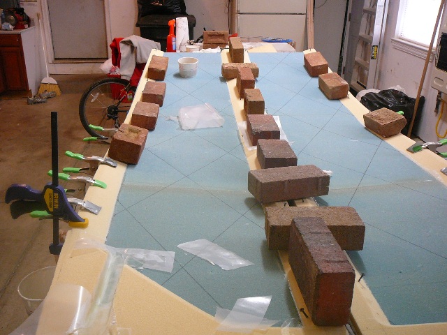
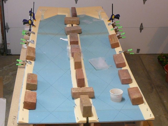
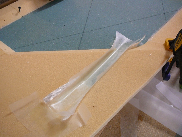
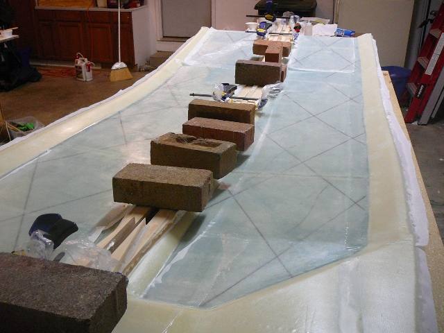
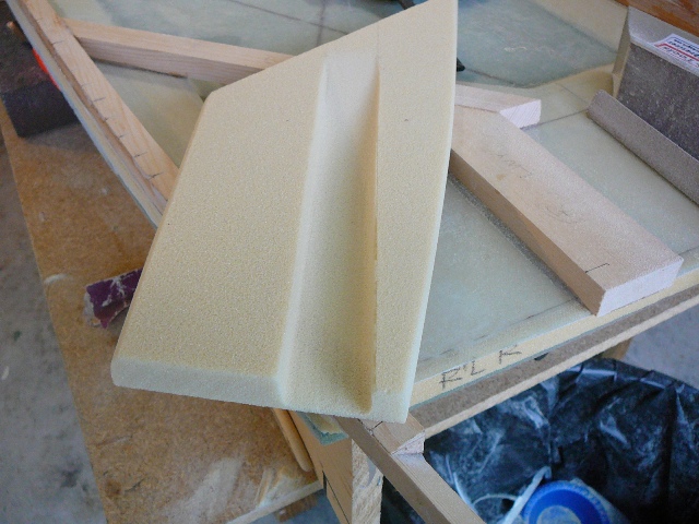
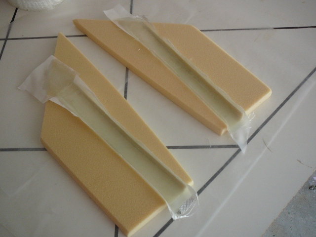
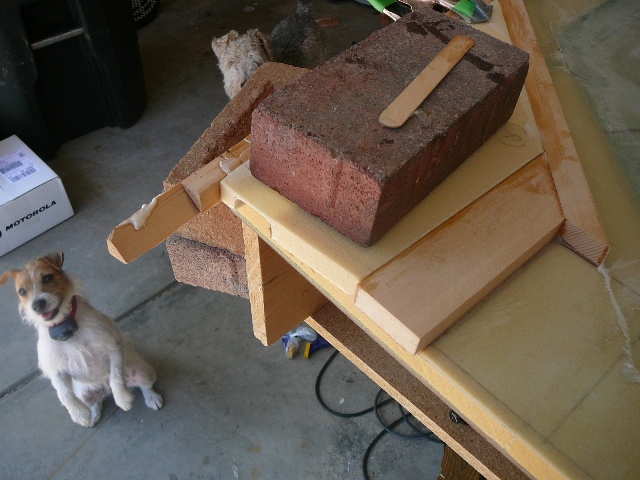
Contouring the InsidesI made a few changes here. Attached the finished spacers per plans using a combination of clamps, drywall screws, and my poor man weights (read "bricks"). I plan on using the Atkinson fuel sights, and decided not to create a depression at this time. From what I've read it seems reasonable to wait, then install after I get the strakes in place. This help to make sure I've got the right placement, and should simplify the lay-up in the next section. I also modified the control stick depressions, making them longer, and slightly higher to soften the slope. I may go to the Cozy Girrrls' Strakes later on, but in case I don't, I wanted the stick depressions to be more subtle than the standard circles. The other change was in the plans order. I went ahead and glassed the electric channels now. Mostly, because I had the time, and I couldn't see the downside of doing it at this junction. |
|
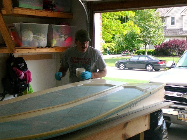
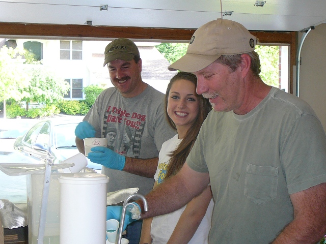
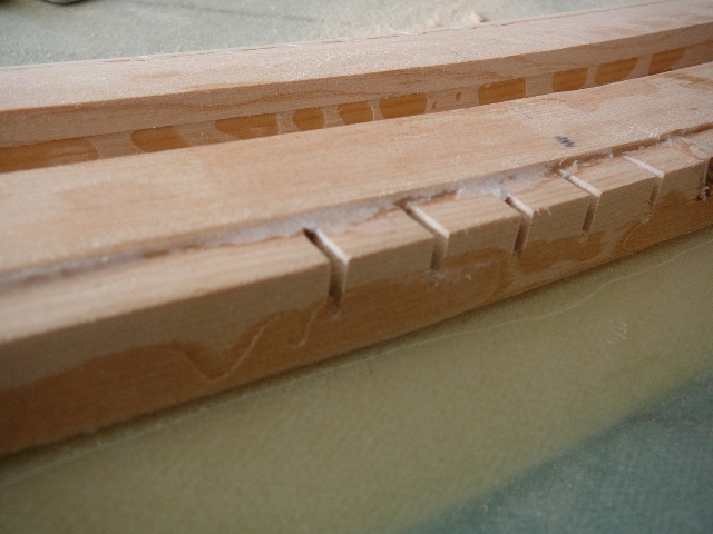
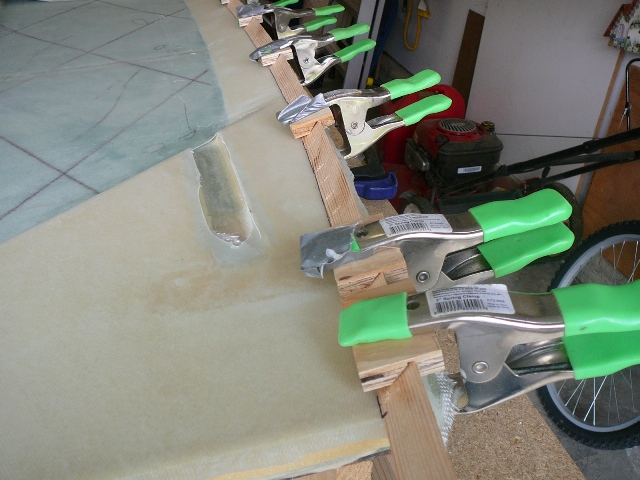
Inside Lay-up and Installing the Upper LongeronsI knew that the "3-hour" reference in the plans had frequently been called out as BS, so I was prepared for a long haul. In fact, I'm pretty sure I spent three hours just spewing expletives. Other than long, things weren't too bad if you took your time. I enlisted the help of my friend Glen (plain grey T-shirt) and middle daughter Paige (the first to actually help work on the plane...although reluctantly) to help put the UND down. Thank you Glen and Paige! Glen also mixed up some epoxy and took a turn with the squeegee. All the prep was straight-forward, the one exception is that since I glassed the electrical channel ahead of schedule, I floxed the corner where the glass-to-glass bond would be. I'm pretty sure this was unnecessary, but I figured it was a good habit to keep, and I think I was subconsciously stalling putting on the UND. The UND was a little akward, and I was glad that I had drawn the 30 degree guidelines. I recommend trimming the edges a little longer than normal to give yourself some "wiggle" room. Once down, I found it easier to work the UNI from the UL spacers toward the bottom. Then before adding epoxy, cut the fabric between the two sides so activity on one side doesn't distort the other. Varied from plans slightly when installing UL's. Before I started the layup I positioned and marked the UL's where I wanted them, then clamped the spacers between them. This allowed me to move them as a set, and it made it very easy to flox them and attach them when the time came. I was happy to say that it worked as well as I thought it would (hopefully I won't be surprised later on). TEN hours later, I finally left the garage!!! Other notes: You may notice that I'm using both a scale and Sticky-stuff dispenser in the picture to the left. Because of the problems with the hardener oxidizing and only one hardener container (requiring you to premix slow and fast as needed), I pretty much only use the dispenser to distribute the resin, and then measure in the hardener using a scale. I would recommend that if you're looking to save a few dollars, don't buy the dispenser. Also, I ran out of slow hardener just as I finished... a good reminder to check your tools and supplies before you start! Despite all the checks, I had a few air bubbles that will have to corrected. Otherwise, the lay-up looked okay. While I waited for the slow hardener to ship from Wick's, I went ahead with the rest of the chapter. I also prepped the UL, in anticipation of the 4 ply UNI lay-up, by filling the saw cuts with wood pieces and rounding the edges along the full length of the UL. |
|
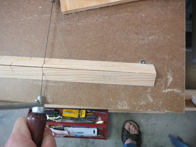
Installing the Lower Triangular LongeronsDeviated from plans by working on LTL's before completing the 4 ply UNI lay-up on the UL's. After removing peel-ply from lower spacers, confirmed and marked the required measurements between the upper longerons and the lower triangular longerons (LTL's). Then prepped the spruce pieces by making relief cuts so the LTL's will conform to the curves of each side. Since the sides curve on two planes, the relief cuts need to be made on both the corner that will be flush against the side, and the corner that will be flush against the bottom (installed in Ch. 6). I used a coping saw, placing a 5/16" block next to the LTL as a depth guide, and cut at the following locations (starting from F22 and working backwards):
Like others, I made some blocks with 45 degree notches so clamps can easily hold down the LTL's, and then test fit each LTL. Confirmed measurements again and marked outlines onto the sides as guidlines for installation. Epoxied LTL's and rear doublers(after LTL's were cured) using clamps (no nails), and cleaned all excess flox from parts. In preparation for the LWX and LWY measured and marked the 5.5" x 8.7" spar cut-out area. Since this measurement is made from the rear line (and UL), you need to know where the forward and rear cut lines are going to be. So I spent a lot of time, measuring and re-measuring the 101.75" fore to aft dimension. Based on what I've read, I expected to make some slight adjustments to the angles on LWX and LWY to get everything to fit properly, so I made the pieces a little longer to allow for adjustment. I was pleasantly suprised when I discovered that very little adjustment was required! Like the LTL's, I confirmed the measurements and traced the outlines as guides, then floxed into place using weights and clamps to secure. |
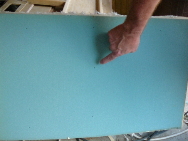 |
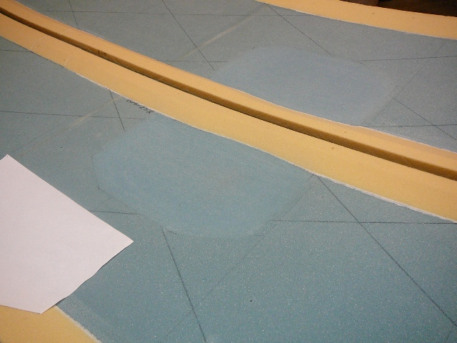
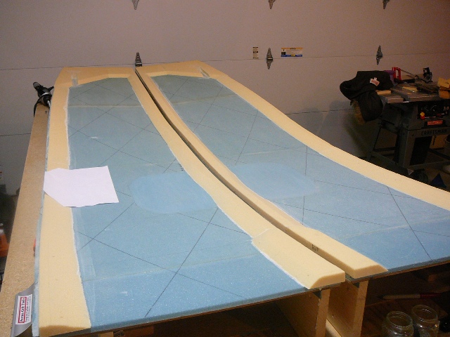
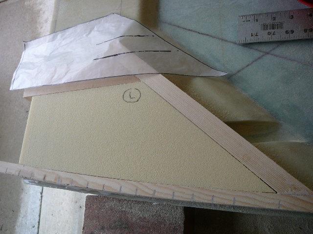
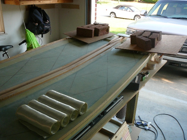
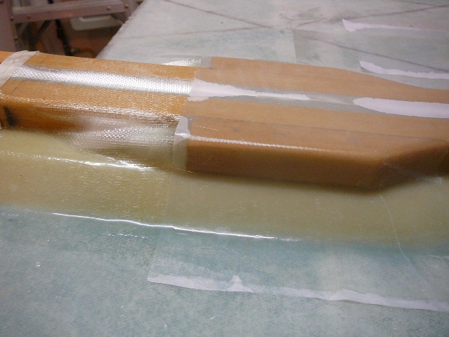
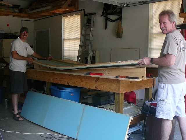
Finishing the Fuselage SidesDeviated from plans for creating the electrical channel and filling the lower rear areas. Instead of creating a mold for the electrical channel, glassing, installing, then filling the surrounding area with 3/4" foam, I filled the area with foam, then created the electrical channel in the foam. To me, this just seemed to make more sense. Used wax paper to create a pattern to cut out the foam. Had a small moment of reassurrance when the pattern fit into both sides equally. Then it was a simple matter of cutting and sanding foam to fit. Once the pieces were cut, measured and marked the channels. Used a razor to score the channel edges, then a combination of chisels and files to finish. Glassed the channel, then set the pieces in with micro (with my two co-pilots watching). Cut BID and completed 6-ply layup over lower rear section. Used packing tape to mask off areas where I didn't want run-off. In the picture to the left, you'll also notice the UNI cut and rolled for the 4-ply layup over the UL's. Completed the 4-ply UNI layup on the UL's. Due to the size, I decided to lay/work one ply at a time versus creating a large multi-ply tape. This worked out fine, as I just took my time and didn't encounter any problems. Since the UL will be cut foward of F28, I didn't worry too much about the glass aft of the forward doubler. I rolled out the UNI from the front doubler keeping the fibers straight. As I approached the rear doubler, I made a small "pinch" of the cloth between the two sides then continued unrolling the UNI. This made it easier to form the glass over the rear doubler. After a 36-hour cure, I removed the peel-ply, cleaned up the part, and the removed it from the jig. Pop, Pop, Pop...the part came right up and only left small holes on the exterior foam that will be easily filled prior to glassing. Since it felt like a milestone,I had my daughter Jillian take a picture of us removing the side (that me with the blus shorts on the left). Then, after a lot of measuring and re-measuring, my friend (Glen) and I completed the sides by trimming the foam and longerons per plans. As a side note - I had a lot of fun playing with the spar section cut-out; in particular, using it to demonstrate that although it was very light, it easily supported my full weight. Even my wife feigned interest! On to Chapter 6... |
Chapter 4 Chapter Index Chapter 6
|
N911HF - No 911 Heroes Forgotten |