Cozy
Chapter 23 - Engine Installation
Intro
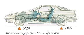 The engine I plan to use in my airplane is an automotive engine. It comes from a Madza RX 7. It is a 1300cc rotary engine. I chose the 4 port turbo model or 2nd generation engine. Aircraft engines are based on technology from the 1940's and haven't made much progress in improving that technology. They have all the parts (like rods, valves, springs and such) that normal engines have but are air cooled. So they are subject to all the possible breakdowns of an engine designed in the 40's. By contrast, the Madza Rotary has only 3 moving parts (an eccentric shaft and 2 rotors). Most failures of this engine have been able to complete its trip. It doesn't "blow up" in the conventional sense. In an airplane this would mean that you would be at a reduced power setting, not "without power" if a failure occurs. What a safety factor that is. However one of the drawbacks of the engine is that it pushes engine oil into the combustion chamber to lube the Apex seals.
Modified for Aircraft Use
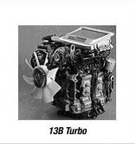 The engine will need to be modified for use in an aircraft!! The engine I have is a 1986 - 88 model that was rated for over 200 HP. But in a car, the concerns of weight and simplicity are not as not as paramount as emmissions and other concerns. And the engine was designed to run from standstill to highway speeds. Whereas in an aircraft, you taxi out put it to the floor, climb to altitude, then back off a little. Once at cruise, you are maybe just a few RPM from maximum, which allows for best speed vs fuel economy. So where you want your best preformance is at high RPM in the aircraft. As an example the "computer" that controls the spark and fuel injectors is set up for giving good emmissions not optimal preformance. A lot of the complexity and weight can be removed. My intake manifold weighs about 50 lbs, a simplified one could be made to weigh about 5 lbs while increasing power.
My Engine
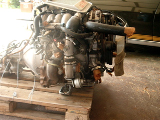 This is the engine I bought off Ebay from Japan. There is a lot of stuff on here that is not needed on an aircraft. Smog and power steering pumps, automatic transmission etc. are to be gone. I found remarkably little damage to any of the internals of the engine. I also picked up a 1990 normally aspirated (it has a Carb) engine to use as spare parts. But when I took it apart, it had a lot of carbon buildup but nothing else to indicate 120,000 miles. I will not be injecting the engine oil onto the apex seals. Doing so causes that carbon to build up ('cause engine oil is not made to be burned). Instead, I will be putting 2 cycle oil into my gas at the rate of 1 oz. per gallon. This will allow the engine to run for much longer without the carbon build-up.
Takin It Apart
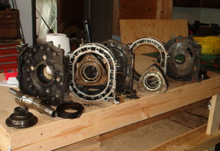 Even knowing that there are only a few parts in ths engine, it was startling to see how easily it came apart and how few parts there really were. You can see end housings, the center housing, the rotors and housings and the eccentric shaft are all the major components.
Porting
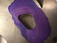 This image shows an intake side port (this allows the air and gas into the engine combustion chamber). I had my engine modified by having a "mild street port". This allows more air and gas to get into the engine, ie. more power for no more risk to the engine. I also had the faces of these sides "lapped" for a factory fresh face. I am also installing higher compression rotors. In all I hope these modifications will net me about 275 HP.
Assembly
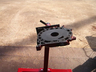 Here I've placed the front endhousing onto the engine hoist. The gear in the center allows the front rotor to turn on the eccentric shaft(crankshaft). There is another gear on the rear housing that does the same for the rear rotor. In this view you can see the intake port and where the intake manifold mounts.
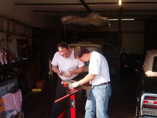 Here one of our local Mazda finatics( my manager, Levent Gokcen) is helping me assemble the engine. We are insuring all the oil seals, rings, apex seals and all the little things go into the correct place.
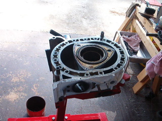 Here the rotor housing has been installed along with the front rotor. The bottom opening of the rotor face is where the combustion occurs, and it is just at the exhaust opening or port(the round hole in the rotor housing). The rotor face closest to you is in the intake cycle, as it rotates away from you, it draws air into the chamber. The third face is in it compression cycle, a little farther and it will fire the plugs(which are on the other side of the rotor housing).
Block
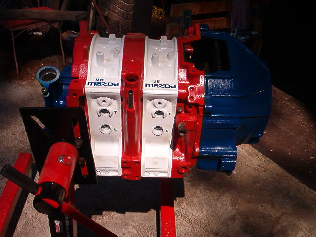 Can you tell what color I will be painting my plane? After painting and assembly of the block, it was looking pretty good! Just waiting on my manifold from Bruce Turrentine. I already have my engine controller from Tracy Crook. My engine mount will soon be shipping from Conversion Concepts.
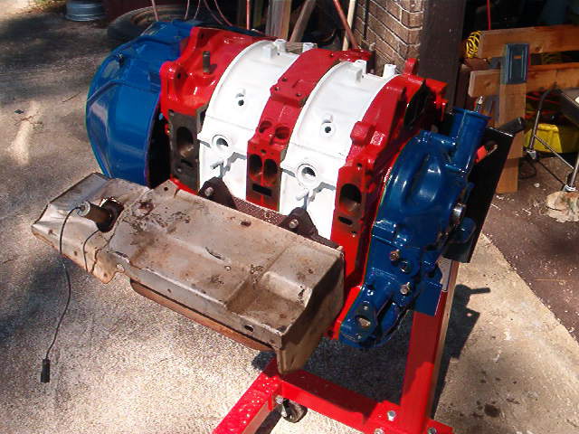 Yep! Intake still missing! Boy do I want to hear this roar!
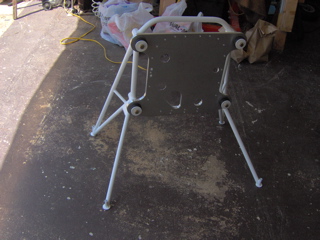
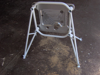 YEEEAAAHHH!!!!! My motor mount finally got here. The top view is on the left and the bottom is on the right. This one is a new style that will allow for the removal of the oil pan without having to remove the engine from the airplane.
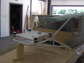 This view shows it in position close to where it would be when finished. Now I can assemble the rest of the engine and place it on the back of my pick-up. I have a mount built in my truck to allow me to test run the motor and try to eliminate some of the hazards of an automotive engine installation and a new plane on it initial test flights. I will also be able to test out may different intake manifolds without a lot of effort. No custom cowlings made every time I want to try a new manifold.
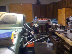 Some people consider this to be pornography! It sure is exciting to me;-) My aircraft engine installed for the first time. Was that good for you too?
Home | Chapters | Links