Cozy
Chapter 13 - Nose and Nose gear
The Plan
In this chapter we will build the nose gear box, which contains the front strut and retraction assembly. There are several bulkheads that crisscross the nose section, this adds strength and then the skin is added to provide an aerodynamic shape.
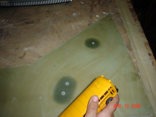
 In the nose there are a lot of bulkheads to make it more able to take the stresses from the landing gear. You start out with the NG-30s. You make the bulkheads then install the hardpoints for the strut and gear. Walker wanted me to get a picture of his bus as well.
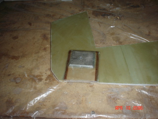
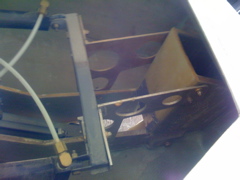
 Fiberglass hardpoints are installed for the gear. I am going to use Steve Wright's actuator, and it only require the original Cozy bolt locations. But notice that the top of the NG-30s are taken to a point, not flattened off. This allows for more reinforcement at the F-22 bulkhead cutout for the actuator.
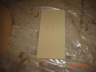 Another one of the bulkheads is the F-5. It is the smallest bulkhead to this point. It goes from one NG-30 to the other above the nose strut.
 This bulkhead is the front of the plane, so to speek. F-0 indicates flight station "0". But in actuality there is about 6" of plane in front of it. This space can be used for ballast, and a lot of other things. My pitot tube and landing light will be here also.
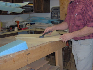 To shape the foam I'm using a bondo sanding rasp. It works extremely well and only takes a few strokes to get close then you use it lightly to acheive a smooth finish.
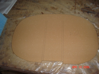
 This is the nose! Finally made it to the front of the airplane! With the F-0 and foward bulkheads in place, you just lay in some foam blocks with 5 minute flox. Once it was dry I wanted to start carving the shape, but was apprehensive because those square blocks don't give a very aerodynamic shape. And I wasn't sure where to start! So I knew the bulkheads were at the proper shape, so that is where I started. Once the foam was smoothed so that it was shaped just like the bulkheads, the rest was obvious. I drew a pattern from the plans of the top, traced it to a piece of cardboard, and used this to do the top.
 Here the sides are put on the nose. The technique they suggested we use,(allow the layup to tack, then fit it and the 2" of extra cloth to overlap the bottom and sides) didn't work well for me. Maybe I didn't sand the sides/mating surfaces as well as I should have or I didn't use enough flox when joining the floor and the sides. Because I had several airpockets the formed and I needed to fix. They suggested we allow enough glass to hang over the edge so we could later use it as the tapes to afix it to the floor, F-22, and F-0. If it was going to work you would have needed to tack it back away from the other mating surfaces. I didn't and it dragged most of the flox out of the joints. I had to later go back in and inject micro to fill the airpockets.
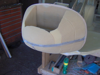
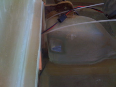
 For the wheelwell, I made a male plug from foam. Here it is fitted in place to check it's fit. The hole that you cut in the bottom sure comes close to the antenna that was buried in the bottom. I'm glad I didn't put a second antenna there because I probably would have place it in front of the other one, and it would have been destroyed when I cut the wheelwell.
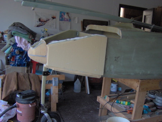
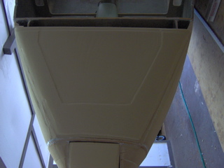 Here is the nose with the foam top installed and ready to glass ( or so I thought). If you look real close you will notice that the copilots (left side in this picture) side appears a little closer to the bulkheads. It is actually about a 1/4" higher. I had the shape correct, just the angle was higher. When I mounted the canard it was obvious. The nose drifted uphill on the copilots side. I had to cut the glass away on that side and sand it to the right shape, then reglass. In the end no harm done, just a little extra time.
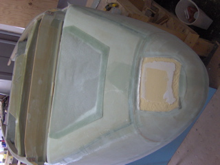 Here is the nose glassed and ready for the rework.
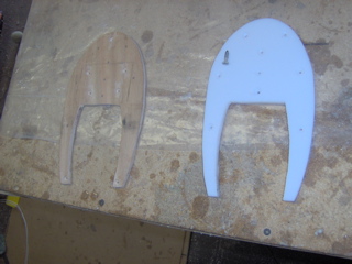 My hockey puck evolved to a system similar to Wayne Hicks'. He used an aluminum plate between the plane and a cutting board. I shaped some birch plywood to a shape similar to the damages most nose draggers experience. Then, I shaped a cutting board to the same shape only slghtly smaller. I will flox and screw the plywood onto the fuselage, then flox and screw the cutting board to the plywood. Then all that is needed is to fair it all in with micro during finishing. Oh, and then hopefully never having to use it except for normal grazing.
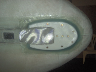 Here the puck is installed and some glass added to reinforce the layup. I put one layer of BID over the plywood then another over the cutting board which I obtained from that walMart aircraft parts store {:-).
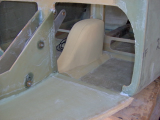
 Here is the finished front wheelwell. The windows for viewing if the gear is retracted or not is very evident when using these;-). That will be the hard part for me! I'll have the windows, an alarm and warning lights, but I bet I'll still miss putting the gear down. That's the reason for the enhanced nose pad.
 The nose gear took enough time from the install making sure the fit is correct. There was getting the gear aligned, then you make the covering and that needs to be aligned, etc. Insuring the wheel retracts straight into the wheelwell was a worry for me. Also getting the wheel doors fitted ment taking them on and of at least a hundred times.
 I am using Steve Wright's gear mechanism. Is it still right to call it a Wright? He has sold the rights to Robert and Valarie. Right on! I'll write them and find out. ;-)
Steve has said there has never been a failure of his mechanism. It is not any harder to install when you are building, but does take a little longer because you need to transfer his plans to the Plan's plans, and understand the differences. In a retrofit there would be some additional work to be done. You need to beef up the supports and cut a hole on one of the bulkheads(f22). Also it is probable that the old hardpoints will not align with his supports.
I am using Steve Wright's gear mechanism. Is it still right to call it a Wright? He has sold the rights to Robert and Valarie. Right on! I'll write them and find out. ;-)
Steve has said there has never been a failure of his mechanism. It is not any harder to install when you are building, but does take a little longer because you need to transfer his plans to the Plan's plans, and understand the differences. In a retrofit there would be some additional work to be done. You need to beef up the supports and cut a hole on one of the bulkheads(f22). Also it is probable that the old hardpoints will not align with his supports.
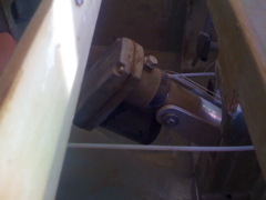
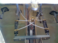 Even when you follow someone elses lead, (Wayne Hicks), installing something they have done still takes you a LOT longer. This brake mechanism went in and out a thousand times. It took way to long to complete. But I'm happy with it! These are Groves, and the attachment mechanism is what took so long. I made several of these until I got it to my liking.
 The support for the brakes was originally only on the pilots side of the NG30s. But no matter what I did, I couldn't get them to operate smoothly and without interference. It took me a while before I realized that I could straddle the NG30s. I then needed to remove foam from them and fill the slots with flox to make hardpoints.
Home | Chapters | Links