| Bill James Varieze N95BJ | |
| February 2005 EZ of the Month |
 |
Bill James is a true innovator and obviously not interested in following the crowd. His Varieze N95BJ has some amazing features, most jump out at you and a couple will make your jaw drop. Be sure to check out the Lightweight Insulated Three Bearing Swivel Module Nozzle Augmentor. 3BSM for short. Will this be the next R.A.C.E winner? Check the results in June to find out. Enjoy the trip as Bill describes N95BJ.
|
||
| Strake airfoil and nose shape. Click on any picture to enlarge it. |
VariEze
N95BJ flew 1400 sm non-stop from Fort Worth Tx. to Reno, landing in Truckee,
Ca. in just under 8 hours at 11.5K, 175 mph, on 31 gallons at 3.8 GPH.
I hope to make the trek again soon with the 0-290. That Oshkosh memory renews appreciation for our country and spurs the recurring sunset emotion, “Burt, the Wright Brothers would have killed to be doing this.” |
Cockpit. Expanded horizons! |

| A
fellow at a fly-in had been studying the airplane and taking notes for a
good while and said, “So, your plane has side windows, wider hip and thigh room (condensed consoles), harmony in pitch and roll; the strakes are aerodynamic, structural, have elbow room in the front seat and baggage space in the rear, thirty-five gallon fuel capacity; the wings are level with no anhedral; there are access panels for the nose, canard, instrument cover, a belly hatch; and those and the wheel pants are held in place with rods—no screws; including the cowls that come on or off in a couple of minutes; cooling plenums, that weird prop… ”So,” he says, “…of all the things on your airplane, what do you like best? The best thing to have on the plane? Bug guts. |
| Modifications |
The bulkheads, spars, and structure materials on my plane are per plans. I have had reason to be very appreciative of the basic airframe and grateful for the elegant genius of the balanced design.
All of these mods passed through a rigorous comparison of efficient simplicity and being lighter than whatever they replaced.
There have been
inquiries as to the source of some of the ideas. I respectfully attribute inspiration
to breathing epoxy fumes until
One in the morning ![]()
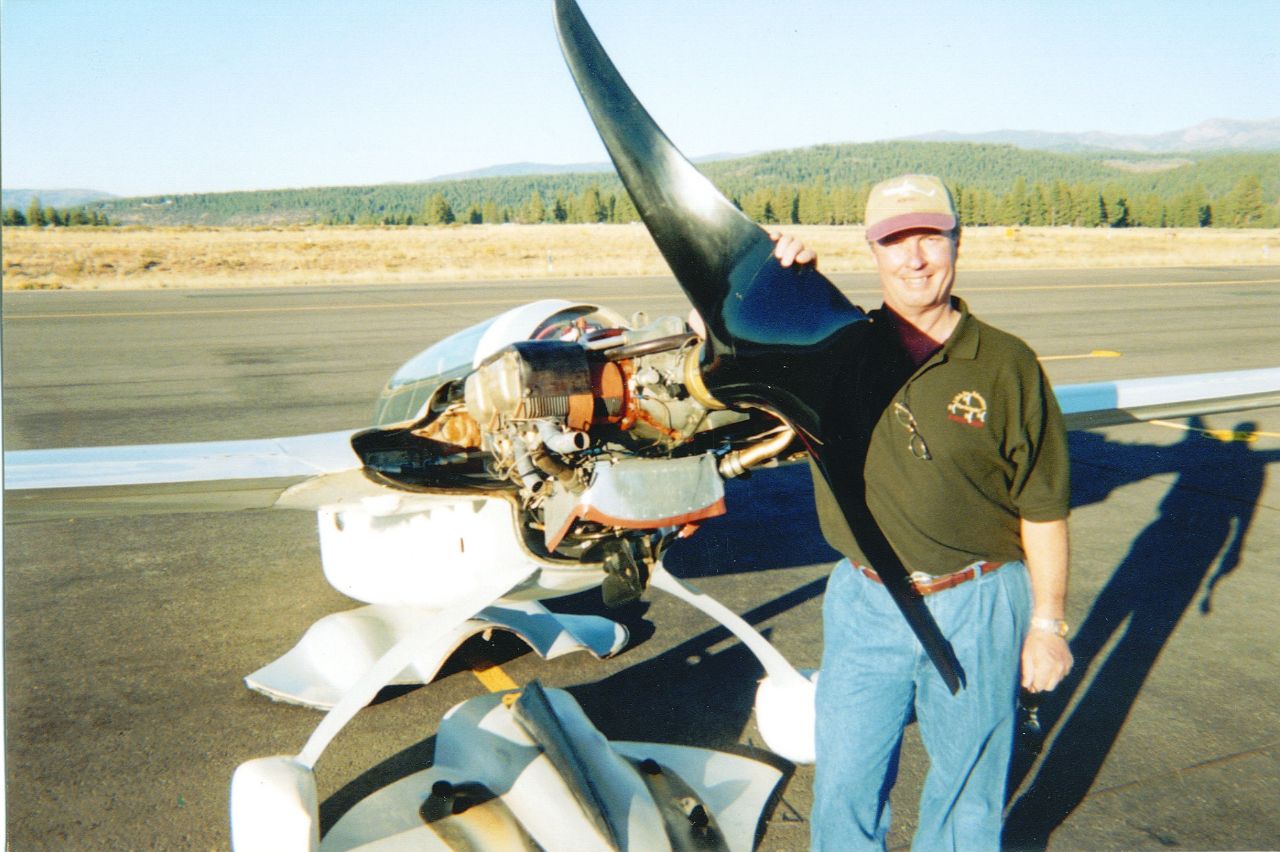 |
The Prop Craig Catto was looking at the prop at Rough River. He wasn't moving and hadn't blinked in a while, so I finally said you could get them at WallMart. He asked the question, “How did you ever even think of that?” After I gave the usual epoxy fumes answer, he said, “No, no, to come up with this prop you would have to roll up the epoxy and glass and smoke it!” The prop has given several hundred hours of problem-free service. I quit tweaking it after it showed a shorter takeoff roll and four more top end mph than a hanger friend’s professionally built 0-235 VariEze prop. The spinner shape is attributable to the desired airfoil/cord goal of ten percent thickness-to-length ratio. So a half-inch thickness would be five inches long, a one inch thick airfoil would be ten inches long. When researching, I was encouraged to aim at taking the ten percent going inward as far as ppractical, and then stay as close as possible, and then just forget it because you can’t do anything in the middle. I was a bad boy, I tried anyway. It was suggested that the flat hub spinner area is a lot of drag as it rotates against the air, kinda throwing air molecules outward like grass from a lawnmower. |
I picked the point that the suggestor touched with his finger, four inches out from center. Calculations at that point on the flat spinner area at 2900 rpm showed the rotational speed at about 69 mph. At 200 mph an air molecule would move outward and aft over the hub cord at about 1 to 3, with mild spanwise flow off the spinner into the relative wind. The image is similar to oil flow patterns I have seen coming off the cowl trailing edges. There just may be some lift, or thrust in this case, in that spinner mix. Some day I’m going to attach some short string to a regular spinnerless aft prop hub and coat it with epoxy and go fly.
With everything
else going on back there, the normal blade sweet spot could expand and move
in some and be relatively a little more comfortable. And if a finned trailing
edge works for wheel pants, shouldn’t the spinner area benefit from the
same purported higher quality trailing edge separation and smoother transition?
Especially on an Eze. So there. ![]()
Am confident that the actual reason the prop worked is pure luck and attributable
to something totally unrelated to anything I have ever actually considered or
conjured up.
Around 1999 I did a forum on my plane for a group of Lockheed engineers. A few days later one of them sent a picture of a 1938ish German wooden flying wing aircraft with two pusher props that looked almost identical to mine. The plane wasn’t successful because of inadequate glues for the airframe but the props were state of the art. He wrote, “You weren’t the first.” Interestingly, several veteran prop benefactors indicate that the best prop info would actually be found in that 1939 jet-infancy time period. I find comfort in the works of my distant kin.
Considerable research led to using several physical techniques related to carbon bonding that anyone would be wise to also get up to speed on. But I don’t recommend that anyone do any of these anyway. ‘Cause then you’d pass me.
The new engine will require a significantly higher pitched prop. Four years ago I built a ‘Son-Of’ backup prop with an aggressive pitch. I over-did it. But now I readily claim having had the foresight to have built up the perfect prop for the 0-290. I meant to do that ?.
 |
 |
| What carb bulge? |
Oh yes, mods…Guiding someone else through the fabrication of one of my mods on their plane is sometime a traumatic affair for both parties.
The normal drill
is:
“So how do I do this?”
“This is how.”
The next day, “Why did you do it that way?”
“Because that’s how you said.”
“That’s not what I said.”
“So how do I make it work now?”
That’s when the epoxy fumes really come in handy.
To make a guess
at the inspiration question,
most normal folks start at what something will look like or do, and if it will
maybe be shiny and hopefully hum, and have a racing stripe. And a few Gb.
Conversely, a different
slant is to drift through the desired function to the basic functional element,
starting the design work reversing through the layers, and only when backing
out of the contraption get an image of what it might look like, maybe in conjunction
with another element, which is often pretty different from what it might should
have normally first looked like to a normal person. And usually prevents the
question “How do I get a wrench or nut on that bolt inside there?”
Maybe that’s close.
Of course, if you do that for a living, it’s easy for you because you’re used to it.
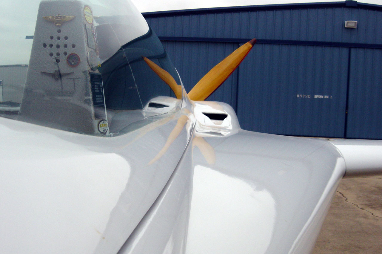
The nose shape is significant! The NG-30
nose strut bulkheads are a couple of inches longer in front of the nose
strut bolt, and about four inches taller. I just didn’t bother to
trim the fronts until after lofting the nose. This explains why folks
stare the first time when looking into the roomier nose area, and why
there is storage room over the canard. The loft of the underside shape
is stock. The nose forward of the disc is hard foam. It is hollowed out with one-inch thick walls. There are access holes in each side of the disc outside the NG-30s. For years I have had expectations of hiding something really exotic in there. Recently I gave up and the transponder antenna was suspended in the nose space with the ground plane bolted to the forward side of the nose disc. I asked a professional aero ez guy what the nose shape should be, round or pointed. He asked if I would be sub-sonic, and if so, a basketball shape would be ideal. Even as aerodynamically beneficial as the rounded shape has surely been over the years ?, a forced cow pasture landing would most likely also result in a happier ending to one’s day. Significant. |
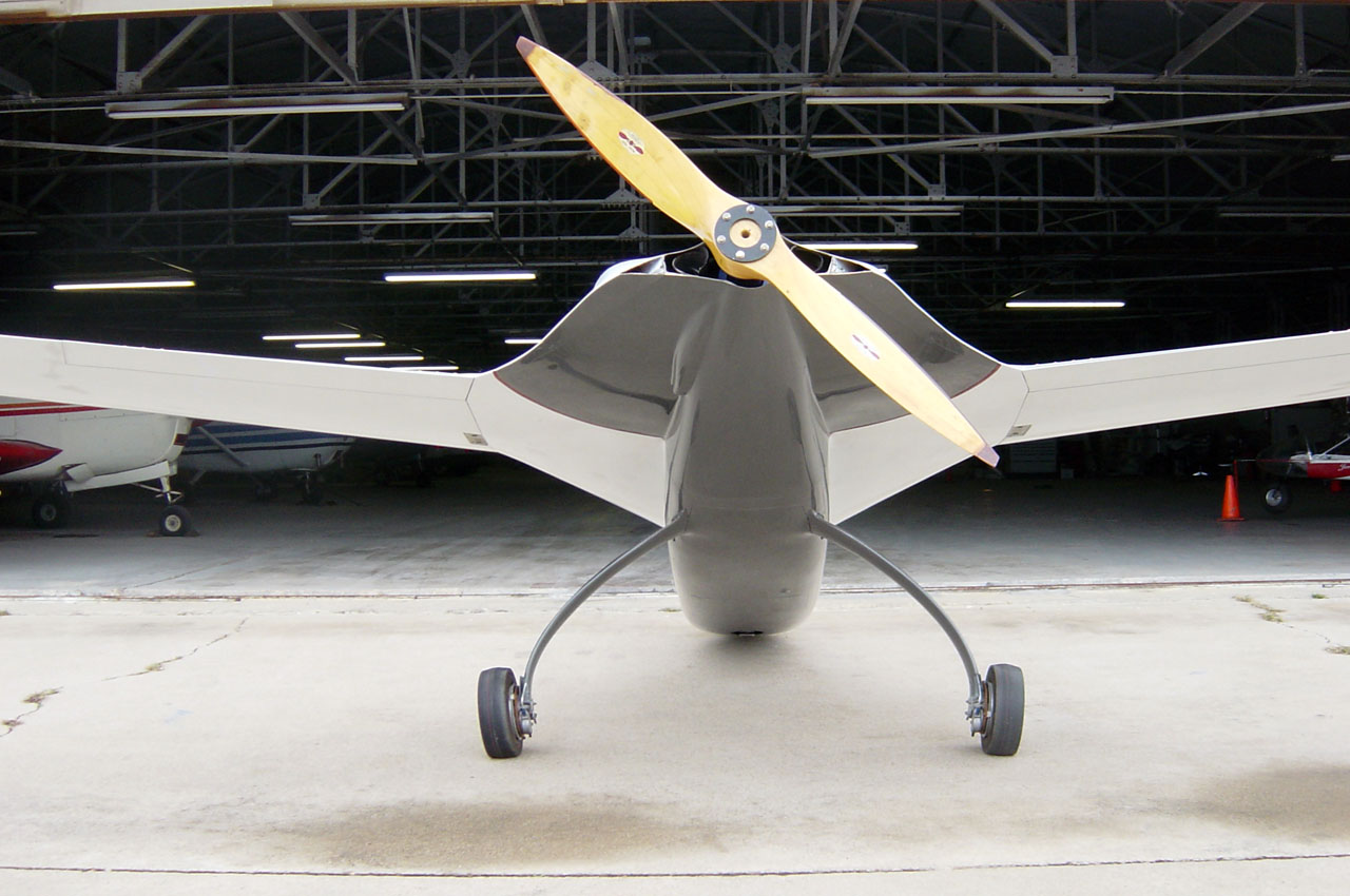
Hanger shot. From left, LongEZ, inverted VariEze with lots of familiar looking mods going on. Far left, brown VariEze in work with familar mods including level wings. Unseen behind, BestBud Dave Perry's VariEze, shinning and humming.
Transponder antenna, suspended in nose. |


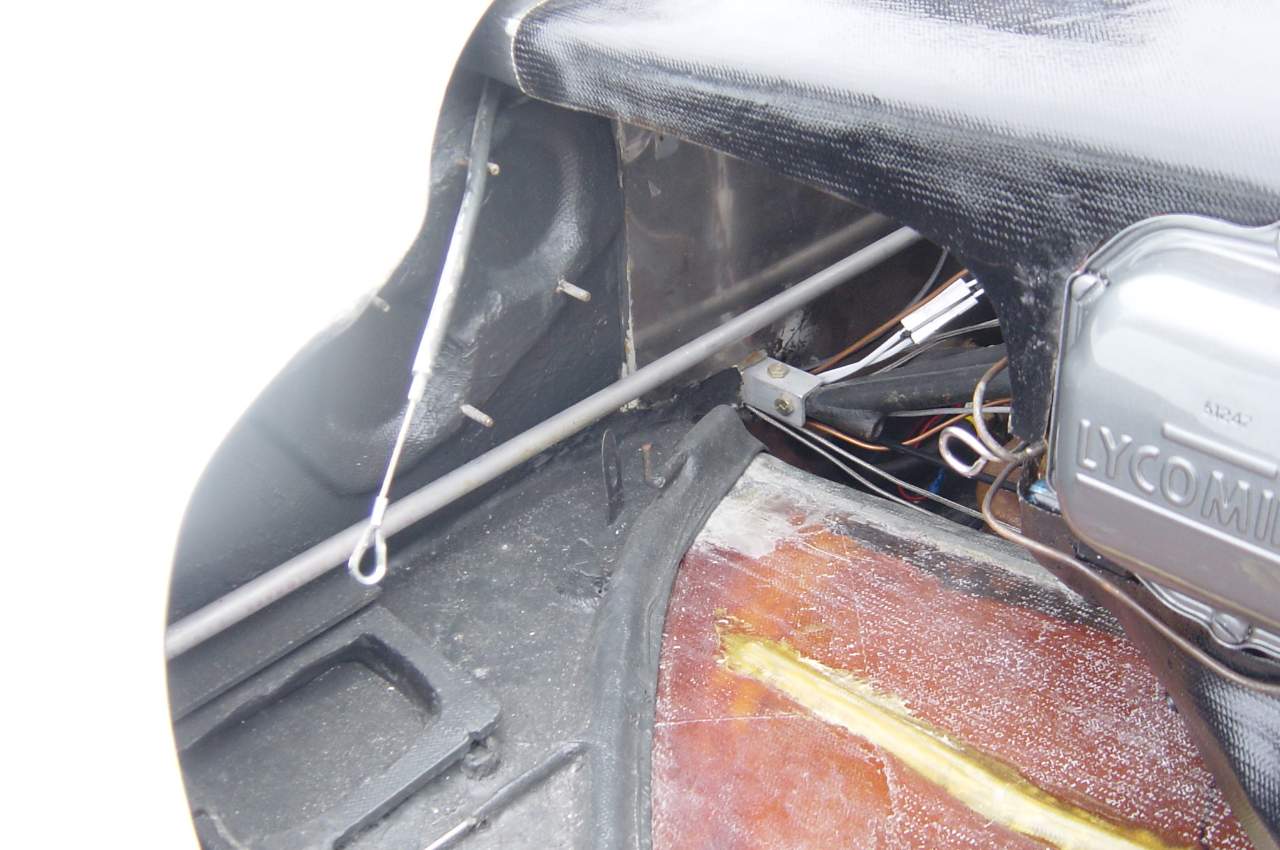
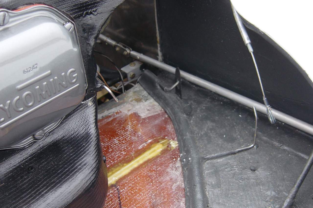
Fuel Instead of just adding a small independent tank, this one was built into the fuselage floor and walls. (I think there’s already fuel “near” the cockpit…) To get maximum volume I sat in the back seat and marked off the wall area under my legs. That portion of the floor was reshaped with a low point and drain. A front wall was installed with wet BID plies. There is a tunnel for the insulated cabin heat tube. The top panel, with a large access hole, was installed with wet corner tapes in and out. The stainless filter, fuel lines, bulkheads and interior details were reached through the beveled hole. Then the 45-degree-cut cover was floxed back in and glassed over. Two half-inch aluminum lines feed freely from the strakes down into the tank. Two additional 3/8 lines connect the under-knee high point of the sump tank to the mid strake area for venting or flow into the sump at different attitudes. Partial fuel can be added to one side and will transfer and balance quickly. Cruise feed balance was matched by adjusting the strake vent lines that exit in front of the gear legs, moving them in or out of the boundary layer. Thtat 1/8 inch adjustment was done once in 1996. The one-piece vent lines cross over from inside the strake, up inside the aft headrest and down in front on the spar to the light of day in front of the opposite gear leg. There’s already strut drag there. Superb fine mesh 1x6 inch stainless screens filter the lines coming down from the strakes. One also surrounds the fuel pickup tube on the sump floor. The1x6 inch stainless filters are for commercial airless paint sprayers. I treat the tank like a reserve supply, without the standpipe or valve. Flight discipline is to be on approach when the strakes have emptied into the five-gallon sump tank. There is a cockpit fuel shutoff to a valve at the firewall. |
Rear Seat Sump Tank |

|
Extended
strakes: The strakes are extended forward to the same point as the LongEZ. The shells are harder and thinner than plans, 5/8 thick high density foam, giving more internal area. They are structural components with interior and perimeter corner tapes inside and outside on the I-beam bulkhead walls and baffles. They are two inches deeper and hold 15 gallons a side. They are airfoil shaped, patterned using Jiran VariEze prefab strakes and molded off the wing. With the strake airfoil template waterline at level, the high point of the top curve is up even with the longerons, giving a little more area and a good high point for the internal vent line. The right strake was installed first, with the left held off until after wiring and controls and such, just before the priming the airframe. The installation is simple, with corner tapes similar to a LongEZ in the seat areas. The surprisingly accessible internal fuel area corner tapes and filter details are easily accomplished through a 14 inch beveled hole in the top of the strake. As described by Ken Miller in his Jan05 CSA strake repair article.
|
| Wing and Canard incidence |
Just when starting to build I discussed some of the above considerations with Mike Mellville, Bruce Tift, Gary Hertzler and a couple of the other heavies at Terry Yake’s excellent ‘90s KC-Gigs near Kansas City. It was confirmed that with the addition of ailerons, the 10.9 inches of VariEze anhedral was no longer needed and level wings would be fine. The extended strakes would be no problem, being totally different than what was causing LongEZ and Velocity deep stall problems at the time.
Having heard VariEze types mention their high AOA cruise attitude relative to the LongEZ, I asked around and learned the difference. And then installed the wing and canard incidence at that of the LongEZ. Now when the canard and wings settle-in where they want to be, the nose is slightly lower, to what I have experienced to be a more desirable lower drag cruise attitude. This is compared to several other wonderful EZs that were flown extensively, including a beautiful LongEZ that I flew for a couple of months, and a VariEze that a friend gave me the keys to for three months in prep for my first flight.
I would incorporate each of the mods again. It makes for an operationally friendly mistress.
| Downdraft Cooling |
All of the above mods were incorporated during building from 1991-95. They came from the fifteen years and four notebooks of ideas compiled while waiting to start. This allowed to a number of mutually beneficial combinations. A ton of ideas (literally) in those notebooks were never used. After first flight I had challenged myself to fly the plane for a year as-is and just travel around and see what the smart fast guys were doing. I did, pretty much. Fall ’96 and summer ‘97 was a great year, including the planets Kanab and Jackpot, and non-stop to the Big O. I figured out what I wanted cooling-wise, but got no help as to how. After enough of wrestling with the stock baffling baffling and erratic cooling, I fabricated downdraft plenums on the 0-235 and started through several iterations of inlets. Checking with the usual suspects had provided no help and I struck out on my own. Initially the 18-inch long male inlet tunnels were made as large as possible, sticking out forward of the cowl, just fitting within the frontal area of the top cowl humps, above the fuel caps in the ramps over the spar. |
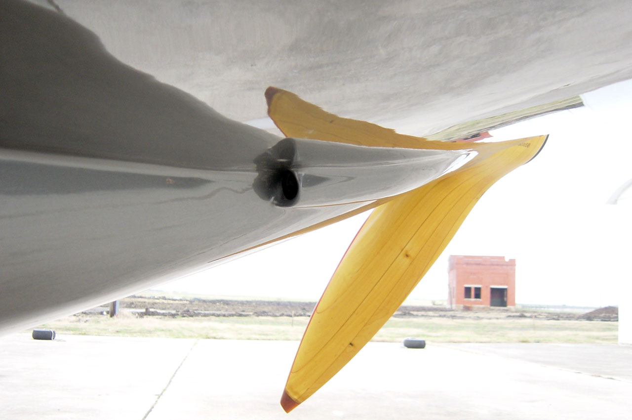
Author's favorite shot, with classic B&T prop. |

 |
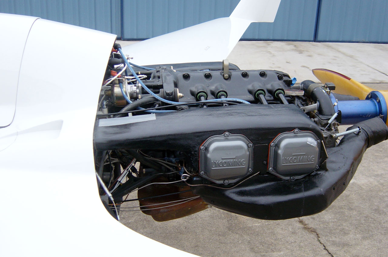 |
| Barrell wraps, cylinder wraps, put the oil in where? | Oblong brown cap near/opposite yellow oil filler is pre-lube port. |
 |
 |
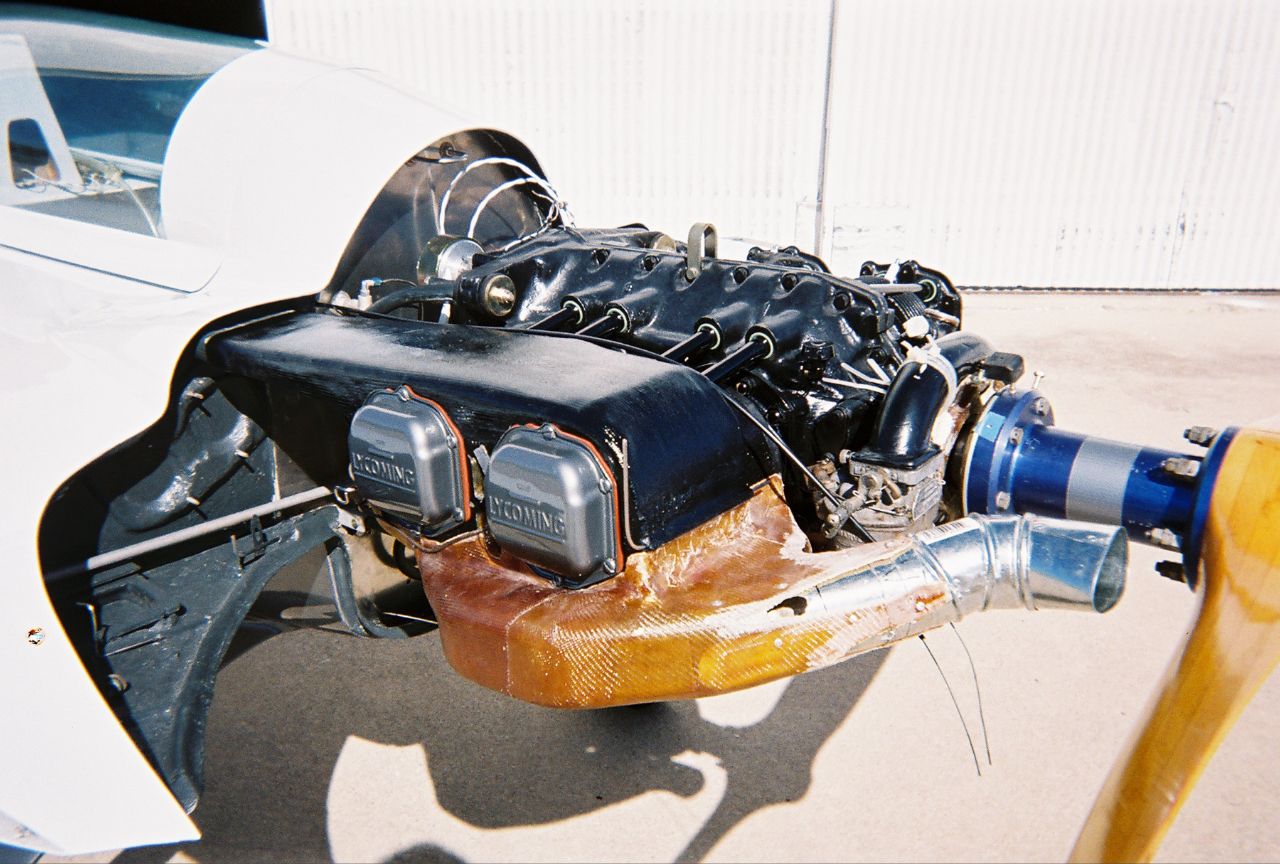
| All dressed up. Yellow cap on case breather is oil filler. |
A by-product of needing this untried system to work was the research gains from prowling the other hangers evaluating carb heat and more productively, the consistent attention spam-canners had paid to low pressure aft of the cylinders. I became more amazed that I had not heard this addressed in the EZ group.
Spam can baffling and especially inlets were crude by our standards, but worked fine. I noted that there was often only one CHT probe and/or very little interest by the pilot anyway. Most interesting was how much of a drag penalty the designers were willing to swallow to get the low pressure below the engine. One Bonanza driver had armament hard points on his one of a kind prototype, and a great story of how he dramatically reduced his CHTs by installing half-round strips on the lower firewall corners.
Augmented
exhaust became a companion interest along with the inlets and plenums.
Today it is an elemental consideration. With that early dd scoop and plenum setup I ran a test course out over the ranches trying to overheat the CHTs. I fabricated new oil and cylinder cooling mods in the evening, curing them overnight and flying them the next day after work. I couldn’t get the CHTs to overheat. As the inlets were gingerly reduced the CHTs were the same or better. An overly-concerned friend had warned me that this plenum chicanery would create severe overheating and cause the pistons to melt and drip out the bottom spark plug holes. But after racing over the hundred degree prairie for a few weeks, I had tried smaller tunnels and was now modifying from the gorilla external scoops to the first of four sets of smaller internal NACA inlets over the spar. He came by and said, “So, you’re having cooling problems, huh? I told you so.” I told him that yes I was having cooling problems… the CHTs were too cool and I was reducing the inlet size, again. At one point a really nifty lift-out slot-fit NACA inlet was finessed into the left top cowl allowing easier access to the oil dip stick. It’s two or three benefits were eventually voted out by a simpler overall scheme. The multiple cooling inlet shapes and locations that were installed and removed indicated that almost any inlet would work—as long as low pressure was generated aft of the cylinders. Over the years and 700 hours, the engine comfortably taxied and cruised through conditions that were a problem with the old baffling. On the hottest days, wide-open high-speed low-level runs wouldn’t even raise a 400 degree fuss. Some said that in a climb the air over the strakes would arch up and starve the inlets. They were wrong. During 90 mph climbs to 12K on 100 degree days, the CHTs would gradually decrease to 320 degrees or less. Normal climb is 130 to 150 mph. I agree that instrumentation can sometimes be questionable. So at one point all four CHT washer senders were installed on the top and bottom of two cylinders. The top, cooler temps were 50 to 60 degrees cooler. In factory types (with dd cooling) most folks quoting factory specs say that the washer CHT senders should be on the top while probes should be installed in the provided lower hole. Using the ‘factory’ location, the CHTs on top read 260 or so. I run washer senders on the lower ‘hot’ side, showing cruise temps averaging 320. So these 320 degree temps are from the worst-case location. Peace of mind. For fun I have and will test probe senders. With two 1 x 5 inch cooling inlets, the tried and true upper plenums interlock with the lower plenums to contain the air around the cylinders and exhausts. Single layer BID wraps orchestrate detailed cylinder fin airflow inside the plenums.
The first gorilla tunnel is still in my memory box. |
|

| Lower Plenums |
 |
 |
| Highlights left plenums, carb intake, oil sump pan. | Inner BID wraps on cyl #2. |
The cowls are not
pressurized and do not require the ongoing detail effort of cowl, aileron gap
and firewall sealing that I was chasing with the old baffling, all just trying
to get the air to go into the cylinder fins in the first place.
The lower plenums (1) contain the heat with fiberfrax and aluminum shrouds around
the exhausts, especially (2) insulating and shielding the lower cowl and paint
and (3) provide a ready carb heat source.
Significantly, in combination with the exhausts, the lower plenums (4) augment
low pressure downstream from the cylinders drawing the air through the cylinders,
like pulling a rope, rather than pushing. During ground idle it is fun to feel
the airflow into the NACA inlet with your hand. Or see a dangled string be drawn
right in.
At Burt’s
Mojave birthday last year, besides crawling halfway into SpaceShipOne, it was
fun to walk the ramp with him a little and listen to his complaining about all
the VariEzes still showing up, “Didn’t these guys get the LongEZ
message?”
I didn’t tell him about the VariEzes still hatching in our hanger.
Wandering the flight line more and looking for downdraft installations, I found seven. I came upon one group that was analyzing a plane and comparing the installation to mine.
Another Eze had simple square inlets in the top cowl, with no internal finesse. I asked the owner about them and he said that he had read an article suggesting that if low pressure was generated downstream of the cylinders as in spam cans, even crude inlet holes would work. I didn’t mention that I’d written the article. He said he tried it and it works fine and he hadn’t gotten around to prettying the inlets up.
| Fire warning |
A light on the panel has an insulated wire going aft through the firewall. At the firewall it twists together with a bare ground wire and goes around the engine. They are not connected. Simply put, melted insulation and contact would complete the ground and illuminates the light. It has been suggested that the light would cause a flustered over-reaction, mental incapacitation and a crash. So far I haven’t had an in-flight illumination to test that thought. Only a couple of power losses, one an engine failure with my wife in the back. With a fifteen minute glide, uneventful landing, supper with new friends, during which my wife wanted to know “what’s a deadstick?” I’ll take the light and earlier warning over the event I heard of where the friends on the ground didn’t have a hand-held.
| Recent work |
The plane is now painted white, with metallic pewter on the belly and lower cowl, with a red, white and blue stripe down the side. Over the years I got attached to the grey primer and decided to keep it around, only in metallic with a clear coat ? It is a pain now because it takes an extra fifteen minutes to wipe off the fingerprints and smudges before locking up the hanger. Wiring and a couple of switches were moved around or replaced. The engine instruments were individually oriented up perpendicular to line of sight. The cockpit is about a third painted. There are a few unconnected lines and cables in the pics.
The main gear is reinstalled at the LongEZ axle location.
0-290 research included hearing comments that it could be installed with “little or no more weight than an 0-235”. The words “about” and “nearly” were mentioned, but probably not enough ?. We’ll see.
| Oil cooling |
Was attacked with an eye on weight. While the downdraft cooling development has been a cool breeze, the 0-235 oil cooling was another story. Mother Nature was not coerced just because ‘I really cared and tried real hard’. Many fine Rube Goldberg elements were installed and removed and now litter a dusty corner in the hanger. Learning day to day, one of my prouder moments was succeeding in getting oil cooler air to come backwards out of one of the most finely tuned NACA inlets I had yet created.
I recently gave a spruced up refugee piece to an F-15 Strike Eagle driver for his birthday. When he asked what it was, I told him I didn’t know, but that it must work really well because when I took it off the plane it cost five knots ?.
For the last few hundred hours the oil temp was great in the winter and OK in the summer. Once level at cruise it cooled down nicely. But the installation was less than fastidious. The oil cooler was located just aft of the spar on a male scoop on the lower cowl. Even with a large cooler and large lines, climbout to 12K on hot days required a stair-step or two for the oil to cool a little. But it worked OK.
A lesser-of-evils summertime addition on the 0-235 had finally cooled the oil temp about fifteen degrees and allowed the normal 130-150 mph climb to 12K. The key was a lightweight aluminum skirt surrounding the sides of the stock 0-235 oil sump. It mainly insulated the oil pan from the warmer-than-usual downdraft lower cowl area.
The aluminum skirt had a red rubber baffle seal on the bottom and sat on the lower cowl. Around the top, slit rubber tubing bumpers prevented chafing. A one-inch air inlet in the lower cowl directed cool air up into the skirt space surrounding the oil pan. The air escaped the skirt around the open top sump flange area.
 |
 |
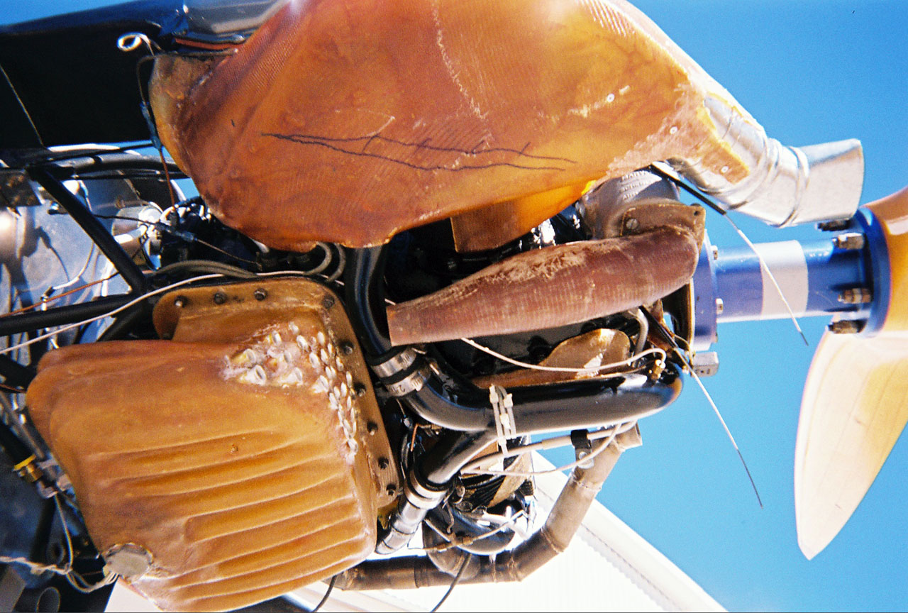
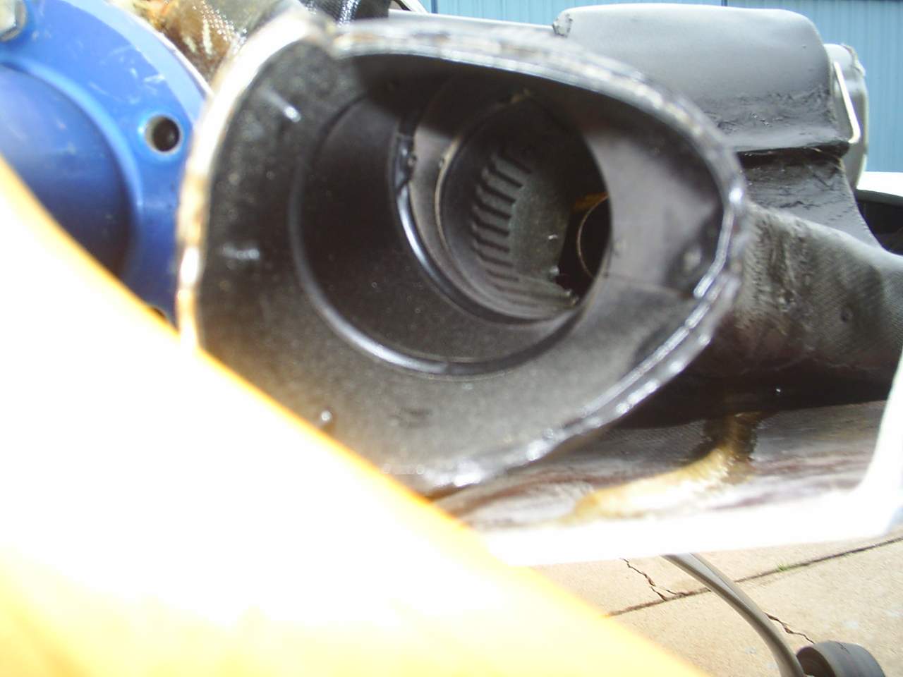
| Exhaust peeking out of lightweight insulated 3 Bearing Swivel Module Nozzle augmentor exit. |
Several folks had suggested that my plenums should have also covered the top of the engine to cool the case, like in a spam can. But I held off, considering installing dual skirts around the lower area under the cylinders. With the existing straight short stack exhausts, the augmentation would have been even better. And now, the lower plenums will contain the cylinder and exhaust heat so the entire cowl area is cooler.
Now, there is no oil cooler, hoses or skirt. The 0-290 fiberglass oil sump has internal “S” shaped cooling tubes, and an area-expanding ribbed exterior that is spaced adroitly next to the cowl, turning the ribs into more tubes. The drain is EZ friendly. The new sump/cooler weighs less than half of the stock sump, oil cooler and hoses and has kept us in the hunt on the weight trade-off game.
Some attention was paid to potential negatives with the sump. The S bend of the aluminum cooling tubes allows for some differential heat expansion. The walls of the sump are four to six layers of BID, with the tube ends in one-inch thick flox walls. That tube wall area is also sealed with fuel tank sealer from an RV friend. The oil level is visible through the walls. Filling is through the modified case breather port. The oil door is the one-minute top cowl.
Air ducting into or out of the tubes has been designed a couple of ways, waiting to see if it will need to direct cooling air in, or use a variable baffle to keep some air out to warm the things up a little ?.
Several knowledgeable friends have helped to evaluate the engine details. I appreciate their assistance and input.
A friendly evaluation
of the oil cooling tubes:
A couple of years ago the three oil sump elements were sitting on my bench.
The mounting flange, center tube/wall assembly, and sump bottom were about to
be glassed together. An older gentleman came through and spent some time measuring
the tubes and other elements. He later returned and stated that twice as many
tubes would be needed to achieve an adequate temp reduction.
So I added fifteen tubes, which also resulted in time for delayed intelligence to kick in for the addition of exterior ribbed surface in proximity to the lower cowl, not only adding more exterior surface area, but also turning that cowl/sump relationship into more tubes.
Recently he came through the hangar again. I had learned that he was a highly regarded retired thermal dynamicist. This time the engine was pretty much together. When he squatted and looked at the oil sump you could see the wheels turning and smell the sawdust burning. He finally smiled approval of the oil cooler/pan.
He ran his fingers along the intake and went from one component to another, tracing through the inter-relations all around and under the engine, tracking the inlet airflow through the plenums around through the cylinders and out the lightweight insulated Three Bearing Swivel Nozzle Module exits. The vertically landing F-35B Joint Strike Fighter I instruct on has one 3BSNM, my plane has two ?.
He kept at it,
and it was impressive to watch him figure it all out. He offered a couple of
cooling opinions and tidbits and then pronounced it a complementary conglomeration
of inter-relationships, with the exception of the too-small carb inlet opening.
He was saying good things so naturally I let him go on till he finished.
A couple of minutes later I explained that at the instruction of an engineer
friend, the carb inlet opening had been specifically sized relative to the size
of the carb venturi. He stared and though a second and slapped his knee in agreement.
I appreciated his comments and just figure we’re both a little crazy.
The oil sump consists of four to six wet layers with attention to the tube areas. I step-cured the plenums and other engine items 50 degrees at a time on the engine by watching the CHT and shutting it off for 20 or 30 minutes. This oil sump and carb inlet expansion chamber (for carb heat) was post cured at home to 350 degrees for two hours at each increased temp. I think you could room temp cure something like the oil sump and then put it in an oven at 350 all at one time and watch it settle into a lump like the Wicked Witch. I made the oil sump attach flange to match the stock one, with a neck so i could reach the bolts with a socket wrench. The drain was optimized after talking with several A&Ps who complained about trying to get the dirty oil out of the flat stock bottom. You also have to make it where it won't suck air at some attitude. I made the middle tube area and then doubled it. Then hot-glued plastic tubes arouond on the smooth exterior and laid up the outer layer on them, and them removed them and glassed the inside.
Several years ago I was talking with Gary Hertzler about how he had flown 2500 miles setting a record. He basically said that I should try flying at 2200 rpm. Soon afterward I went to a flyin in OK and left with 8 gallons for the 1.5 hour trip back, planning to stop at one of several places for fuel. I climbed and set the rpm at 2200 and felt really slow. The ground speed was 155 but I was used to skippin along a little brisker. But I slogged along. Half way home I was planning to descend for fuel but the fuel level hadn't moved. So I went on to the next airport. And the same thing, the level had hardly moved. Finally I just decided to skirt around and land at home. I was in fact "on approach" when the fuel disappared from the sight gauges, and landed with four gallons.
I wrote Gary and told him
that there was in fact something magic about the 2200 rpm; that I had left Ok
with 8 gallons and after 1.5 hours landed with 11 gallons.
Gary wrote back- "Bill, you should recheck those numbers."
| Induction The arrangement is aimed at optimized lean-of-peak cruise. The carb doesn’t stick out of the bottom cowl any more. Several carb locations were explored that would have provided longer mixture time than the stock three or four inches. This aft location fits well into the overall scheme and opened up several other inter-relationships. The carb intake expansion chamber houses a simple and capable carb heat. The spiral intake tube around and under the crank flange gives a longer mixture run. The spider goes with the flow and spins off in firing order. The cylinder intake tubes are tuned. |
Carb inlet
Carb heat |

Cowls and such:
A fun drill when arriving at a fly-in is to set the plane on the nose and pull
the forward pins and remove the instrument cover, canard cover and nose panel
for a full view. You can see the brake cylinders mounted up under the canard
inside the NG-30s. Off-coast sectionals are kept in the canard cover in a ziplock
bag. Walls on the canard cover keep items contained. I am going to place a large
picture of a really impressive wiring setup inside the instrument hatch, over
the wiring ?.
Then I ask if anyone has a stopwatch so they can time the cowls coming off.
Of course there are plenty of impressive aviator wrist watches. So far I have
been able to get the cowls off before anyone figures out how to start their
stopwatch.
 |
 |
| Left cowl attach rod lock and pin. | Right cowl attach rod lock and pin |
 |
 |
| Cowl tube interlock detail | Oil pan cooling tubes, female attach detail. |
Where's the screws?
The cowls have
always had an interlocking flange type of arrangement rather than screws. They
were initially built with multiple sections of interlocking extruded hinges
with cables. The installation was fun and worked well except the metal hinge
elements wore.
Considering several observations including high and low pressures on the cowls,
a new male/female tube perimeter interlock was envisioned … epoxy fumes,
1am … with better strength, fit and wear properties. This current design
is operationally friendly, well proven and is perfect for my purposes.
With respect to
my purposes, the VariEze has provided a platform for severe personal inspiration
and application. My kids have seen that a complex long term goal can be attained.
They saw the fifteen years of delay before diving into the project, working
two jobs to get the engine, and recently a lot of time spent many hours away
from the hangar with my dad during his last couple of years.
The sunset runs are invaluable therapeutic sessions. Time in the garage and
hangar has certainly kept me out of a lot of trouble I’m sure. The pilot
instructor time with the airlines and now with a fighter program are directly
linked to unexpected developments and relationships spiked by having built and
invested energy in the plane. Not to mention the experiences and events that
didn’t even get me a job or anything, only the amazing exuberance we have
all felt lofting through the clouds and being astounded that the rest of the
world down there could even stand to live their lowly lives not being up here
and doing this.
Often when I got
home at noon from somewhere like Rough River or Big O, while unpacking things
on my bed I update the five-foot map and think, “Man, was that a dream
or was I really way out there this morning…”
I am expectant that the ez environment will energize future ballets of wits
and challenges and activities that for many for us will keep the ole noggin
scratchin and scrappin and more alive.
I joke about the epoxy fumes and dumb luck and the sunsets. Over the years, and an anticipated activity now, is to see how long it takes after my request for the maker of the molecules to provide a solution. On a Saturday a few weeks ago designing and fabricating the carb heat, over the morning, the many answers came back as usual, in seconds.
Years ago I had been looking in the garage for weeks for the blank data plate so I could have it engraved for the FAA inspection, a couple of days off. It was in a little packet that had come with the big stack of boxes five years earlier. I was thinking “Lord knows where the heck that little envelope is. I leaned on the washer and whispered for a little help. And heard a noise behind me. One of several small 1x4s that had been in the rafters for years had shifted and fell a few inches. I got on a ladder and lifted the 1x4 back into place and off of a little metal box. In the box was the data plate. Then I remembered putting it there so I would know where it was.
Because of a few things bigger than inlets and data plates, the sunsets are more than therapy. Oh yes, how
much speed have all the mods wrought? |
 |
But at the RACEs the wind, tall motor homes, altitude, terrain and white knuckles on the loose nut on the stick combine for the perfect standard of “the first one back wins.” My Jackpot ‘97 speed was 185 mph. The 2000 Jackpot speed was 201 mph.
Just the thought brings back stomach tightening “I’ll get you next year” frustrations, due to both times having run horrible race strategy. But equally horrible and thus a useful indicator. Both times I held Beagle off until the last ridge where I had to climb and he easily grinned by with his turquoise veteran nose a leetle lower descending from his higher experienced perch. Experience pays. But the RACE events are spectacular and the sixteen mph improvement was encouraging.
The best I can document a few things, Unique trailing wheel fins were installed for the first year and during the first Jackpot (pics in CSA Oct ’97). I really liked them and still have them handy. They were +8 mph over bare wheels and were practical in many ways. Preflight was great and you could stand on the tire to reach in the back seat. Wheel pants showed +12 mph, or + four mph over the fins.
So considering that four mph leaves a twelve mph gain from ’97 to 2000 with the plenums, smaller inlets and a little cowl tightening. And from 2000 till now I will claim further untold wild speeds while I can… but like everyone else will succumb to the proof of the next Jackpot or hopefully Wendover pudding. I’ve already mentioned to my wife that for the first time I expect to be out west on our May 27th anniversary.
|
The big carrot is always cooling drag. That juicy 30% just dangles out there too big to be ignored. But in the end when the last cooling half-knot has been wrung out and ‘exhausted’, I believe that some opinion adjustment will have to be made, moving some of that 30% cooling drag over to other likely excuses. I look forward to someone googling up the source and specifics of that data. And what would a 10% or 20% cooling drag reduction translate to in speed anyway? To ease my mind I just relax and think of the fourteen square inch frontal area instead. Periodically a hopped-up LongEZ and I pair up here for sunset photo ops. Several times he has had new wheelpants or something and challenges for the run back. The last time out I got the best of him again. Back on the ground I told his GIB that the LongEZ driver was certainly cool and disciplined because he had never said anything to me about pulling away from him. His GIB said, “Oh, today he had plenty to say”. Bill James, Fort Worth VariEze |

| Contact | Webmaster |
| EZ Home |